A mm-Wave Circulator with High Transmitter and Receiver Isolation (Part 2)
David W. Porterfield, Ph.D.
President and Founder
Micro Harmonics Corporation
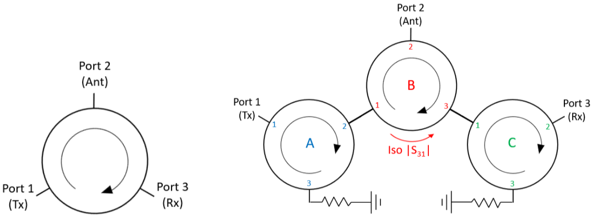
In last month’s blog, I showed why a triple junction circulator offers no advantage over a single junction circulator in isolating a sensitive receiver from a high-power transmitter (S31). I also showed that the new Micro Harmonics hybrid circulators [1] can achieve much higher levels of S31 isolation than Y-junction circulators and over broader bandwidths. Single and triple junction circulator schematics are shown in Figure 1, with typical connections for a transmitter (Tx), receiver (Rx), and antenna (Ant). These port conventions are used consistently in this blog.
Schematic Comparisons: Single vs. Triple Junction Circulators
Multiple Y-junction circulators can be combined in a single waveguide block to achieve higher isolation levels. A schematic of a triple junction circulator is shown below. The three circulators are designated “A”, “B”, and “C”.
Figure 1 – Left: Schematic for a single junction circulator showing transmitter (Tx), antenna (Ant), and receiver (Rx) connections. Right: Triple junction circulator schematic.
Circulators “A” and “C” are essentially isolators.
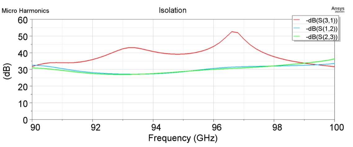
HFSS simulation data are shown in Figure 2 for a hybrid circulator covering the 92-98 GHz radar band. The isolation of the receiver from the transmitter (S31) is more than 35 dB across the band from 92-98 GHz. This compares favorably to triple junction isolators that can only achieve 18 dB isolation of the receiver from the transmitter over the same band.
Figure 2 – HFSS simulation data of a hybrid circulator designed for maximum |S31| isolation at 92-98 GHz.
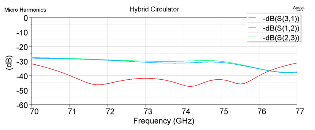
Simulation data are now shown for three more bands. The first two bands are the 71-76 GHz and 81-86 GHz bands, which are targeted for 6G/7G backhaul applications. The HFSS simulation data in Figure 3 show that the hybrid circulator achieves more than 40 dB isolation of the receiver from the transmitter (S31) over the 71-76 GHz band. A Y-junction circulator can only achieve about 20 dB S31 isolation over that band.
Figure 3 – HFSS simulation data of a hybrid circulator designed for maximum |S31| isolation at 71-76 GHz.
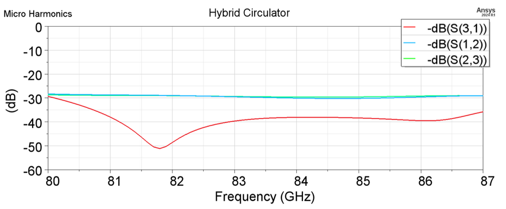
Figure 4 shows simulation data for a hybrid circulator designed to cover the 81-86 GHz band. The isolation across the 81-86 GHz band is nearly 40 dB. With a little more time to optimize the design, it is very likely that S31 > 40 dB can be achieved. For a Y-junction circulator, the S31 isolation is limited to about 20 dB over this band.
Figure 4 – HFSS simulation data of a hybrid circulator designed for high |S31| isolation at 81-86 GHz.
Overcoming Limitations of Y-Junction Circulators
Another problem with Y-junction circulators is that they are difficult to tune at higher mm-wave frequencies above 100 GHz. For example, the center frequency of a Y-junction circulator designed to operate at 160 GHz changes by ± 3 GHz when the dimensions of the ferrite vary by ± 4 microns. This high level of sensitivity makes it difficult to get the thing tuned to the proper frequency. The 20 dB bandwidth at 160 GHz is only about 3 GHz, so if the ferrite dimensions are off by 2 microns, the 160 GHz design frequency doesn’t even lie within the 20 dB operating band.
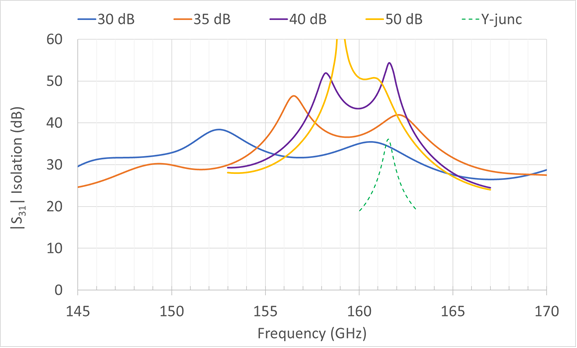
The hybrid circulator is much more tolerant of dimensional variations and is inherently more broadband. Figure 5 shows HFSS simulation data for hybrid circulators optimized for high S31 isolation in D-band. The models were optimized multiple times to see how much bandwidth could be achieved at 30 dB, 35 dB, 40 dB, and 50 dB. Measured data from our 160 GHz Y-junction circulator are shown for comparison. The Y-junction was designed to have a center frequency of 160 GHz but peaks at 161.5 GHz because the ferrite dimension is about 2 microns too small.
Figure 5 – HFSS simulation data of hybrid circulators designed for various levels of |S31| isolation in D-band. Measured data from our 160 GHz Y-junction circulator are shown for comparison.
The hybrid circulator has more than 30 dB S31 isolation in the band 145-163 GHz. More than 35 dB isolation is achieved from 155-164 GHz, more than 40 dB isolation is achieved from 157-162 GHz, and more than 50 dB isolation is achieved from 159-161 GHz. The 50 dB model is very sensitive to dimensional accuracy and might be difficult to achieve in practice. But it is clear that our hybrid circulator can be tuned for much-improved performance compared to a Y-junction.
There is an inherent asymmetry in the hybrid circulator, which is explained in a paper published in the IEEE Transactions on Microwave Theory and Techniques [1]. The blue (S12) and green (S23) isolation curves in Figures 2-4 are at the 30 dB level, while the S31 isolation data are much higher. The blue S12 curves show the isolation of a transmitter attached to port 1 from a signal entering the antenna on port 2. The green S23 curves show the isolation of the antenna on port 2 from a signal originating from a receiver attached to port 3. An isolator can be attached to port 1 to increase the S12 isolation to more than 50 dB. Similarly, an isolator can be attached to port 3 to increase S23 to more than 50 dB. As shown in the previous blog, a triple junction circulator achieves the same type of increase in S12 and S23 since two of the circulators have their third ports terminated, turning them into isolators. This can be seen in the right-hand schematic in Figure 1. However, there is no way to increase the S31 isolation in the triple junction.
Advancing mm-Wave Technology with Micro Harmonics
The new hybrid circulator technology from Micro Harmonics is inherently broadband and capable of achieving levels of performance far beyond what is possible with Y-junctions. We have demonstrated in D-band (110-170 GHz) that the hybrid circulator can cover entire waveguide bands with 20 dB level isolation. Our full-band 110-170 GHz hybrid circulator is available for sale. To date, we have not actually built and tested the high S31 isolation variants of the hybrid circulator, but it is just a matter of time. We have a lot of experience designing hybrid circulators and a high degree of confidence in our models. The hybrid circulator is protected under US patent 12034196. A patent is pending in Europe.
If there is anything we did not cover here, or in case you have any questions regarding our other products, such as isolators, attenuators, or orthomode transducers, please don’t hesitate to reach out!
If you haven’t read Part 1 yet, we encourage you to give it a read: A mm-Wave Circulator with High Transmitter and Receiver Isolation (Part 1).
References
[1] D. W. Porterfield, “Broadband Millimeter-Wave Hybrid Circulators,” IEEE Trans. Microw. Theory Techn., vol. 71, no. 8, pp. 3501-3507, Aug. 2023.

