
Advantages of the Hybrid Circulator
Introduction
Circulators are 3 port components that couple power in a circulating fashion: power from port 1 is coupled to port 2, from port 2 to port 3, and from port 3 to port 1. Circulators are widely deployed in communications and radar systems because they enable a system architecture whereby a single antenna (or array of antennas) can be used for transmission and reception. Figure 1 illustrates a possible transmit-receive system realized with a traditional Y-junction circulator. An isolator is sometimes used in front of the receiver to block reflected signals from propagating to the transmitter.
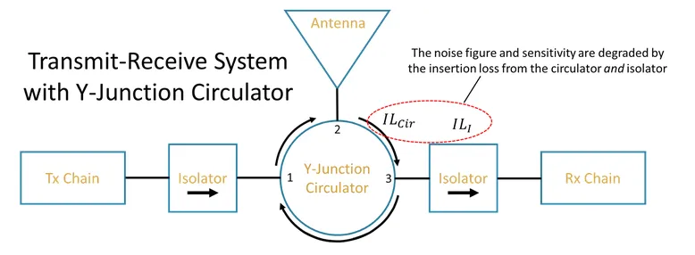
Figure 1: Example of a transmit-receive system realized with a Y-junction circulator.
The Y-junction circulator has been the dominant technology at high frequencies for many decades. Unfortunately, the Y-junction circulator bandwidth decreases as frequency increases. A well-tuned Y-junction circulator has a 20 dB fractional bandwidth near 10% in the WR-15 band (50–75 GHz) but the fractional bandwidth drops to 2% in the WR-5.1 band (140–220 GHz). Y-junction circulators are very difficult to tune at the higher mm-wave frequencies because the fractional bandwidth is small, and the center frequency is highly sensitive to the ferrite core dimensions.
Micro Harmonics recently developed a new type of circulator that has significantly greater bandwidth and higher frequency coverage than the traditional Y-junction. Their “hybrid” circulator comprises a Faraday rotator and an orthomode transducer which work together to achieve the circulator function. Their initial line of hybrid circulators employs asymmetric OMTs which enables an astounding 24% fractional bandwidth. In theory, a symmetric OMT can be used to achieve full rectangular waveguide band operation (40% bandwidth). Another important advantage of the hybrid circulator is that the bandwidth does not degrade at higher frequencies like the Y-junction.
Bandwidth and Frequency Coverage
When it comes to bandwidth, more is better. In communication systems, the theoretical capacity for a given channel is directly proportional to the channel’s bandwidth because the capacity is governed by Shannon’s theorem:
![]()
where C is the channel capacity (maximum theoretical data rate), B is the channel bandwidth, S is the received signal power, and N is the total channel noise power across B. So, in communication systems, the wider the bandwidth, the higher the available data rate.
In test and measurement, the bandwidth specification can be limited and constrained by the most-narrow band component in the system. Wideband test equipment can be used in more scenarios and therefore wide bandwidth subcomponents are often advantageous. Similar arguments could be made for other technologies such as radar and remote sensing.
A comparison between the fractional bandwidths of the hybrid circulator and a Y-junction circulator will clearly demonstrate the superiority of the hybrid circulator’s bandwidth. Fractional bandwidth is expressed as a percentage and defined as:
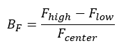
where Fhigh is the upper cutoff frequency of the component, Flow is the lower cutoff frequency of the component, and Fcenter is the center frequency of the component—the arithmetic mean Fcenter = Fhigh + Flow
2. For reference, full waveguide bands are defined at around 40% fractional bandwidth.
Please note, at the time of this writing, the author could not find any extant Y-junction circulators in WR-6.5, WR-4.3, or WR-3.4. (Micro Harmonics designed a WR-5.1 Y-junction circulator for reference, but manufacturing commercial Y-junction circulators at these frequencies is not feasible). Figure 2 below shows the fractional bandwidth of the traditional Y-junction circulator and the hybrid circulator for comparison.
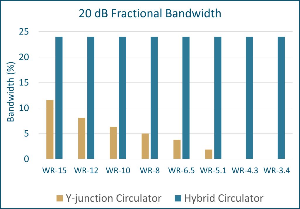
Figure 3: Example of a transmit-receive system realized with a hybrid circulator.
Not only does Figure 2 demonstrate the superior bandwidth of the hybrid circulator, but it also shows that the hybrid circulator is an enabling technology for higher frequency systems. Until the release of the hybrid circulator, there was no component on the market at WR-6.5 or above that provided the 3-port circulating functionality. Now there is.
Architectural Simplicity
Another feature of the hybrid circulator is that it can be configured so that the transmitter port is internally isolated from the receiver port. To understand why this is helpful, first look back at the transmit-receive system in Figure 1. Isolators are placed on both the transmitter and the receiver ports to reduce the signal power reflected to the transmitter. In a Y-junction circulator, signals reflected at the receiver are coupled to the transmitter port which is why a receiver port isolator is sometimes required. Figure 3 below illustrates a possible transmit-receive system realized with the hybrid circulator, rather than a traditional Y-junction circulator.
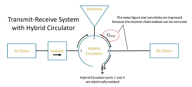
Figure 3: Example of a transmit-receive system realized with a hybrid circulator.
Comparing this setup with the setup in Figure 1, it can be observed that the isolator in the receiver chain was removed. The isolator is no longer necessary since port 3 does not couple power to port 1. This example illustrates one way that the hybrid circulator can act as a 2-for-1 component. In these scenarios realizing a system with the hybrid circulator will save space and simplify the system architecture. It should also be noted that the ability to remove an isolator before the receiver chain will reduce the total insertion loss thereby improving the noise figure and sensitivity of the receiver.
Sometimes the wider bandwidth provided by the hybrid circulator results in a simplified system architecture. One example of this would be a point-to-point communication system in WR-12 which is required to cover the two popular unlicensed sub-bands, 71–76 GHz and 81–86 GHz. A Y-junction circulator would struggle to cover any one of those sub-bands, whereas the hybrid circulator can cover 70–86 GHz, encompassing both sub-bands. Not only does this reduce the number of total circulators required from 2 to 1, but it will have repercussions on the rest of the system design, saving space and cost elsewhere.
You can find more details about the hybrid circulator here. You can find a summary of the performance of our hybrid circulators and their spec sheets here. Feel free to reach out to Micro Harmonics at sales@mhc1.com if you have any questions.