
Why Are Y-Junction Circulators Difficult to Find Above 100 GHz
Y-junction circulators are used to direct signal flow in millimeter-wave (MMW) transmit and receive systems. At the heart of the device is a ferrite core located at the junction of three waveguides. The magnetically biased ferrite is non-reciprocal which gives rise to the unique circulator behavior. Commercial circulators with full waveguide band operation are available up to 40 GHz, although the isolation is generally less than 16 dB. Above 50 GHz the bandwidth is severely limited due to limitations in the ferrite material properties. Figure 1 shows measured 20 dB bandwidths for Y-junction circulators operating at the WR-15 (50-75 GHz) through WR-5.1 (140-220 GHz) bands.
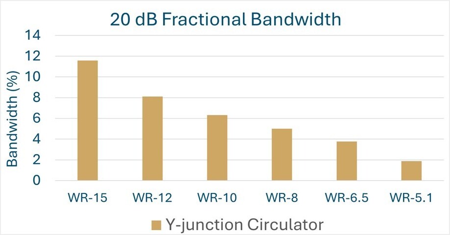
Figure 1 – Measured bandwidth for Y-junction circulators produced by Micro Harmonics. The 20 dB bandwidth is defined as the band over which the isolation between ports is more than 20 dB.
Above 50 GHz there are relatively few vendors and most of the advertised circulators are special-order offerings. The narrow bandwidth makes them unsuitable for many systems, forcing undesirable bandwidth limitations. Since they don’t cover full waveguide bands, multiple designs are required within each band. For example, in the WR-6.5 band the typical bandwidth is about 4 GHz. In order to get some overlap, you might design them at center frequencies spaced at 3 GHz apart, so you would need about 20 unique designs to cover the WR-6.5 band. The Y-junction circulators are highly-tuned cavities and they do not scale readily. A separate optimization would be required for each of the 20 designs. The cost of machining is prohibitive for small quantities, so you would probably have to fabricate at least 5 waveguide blocks for each of the 20 designs. The ferrite dimensions would be slightly different for each design, so 5 x 20 ferrites would have to be fabricated. You get the point. Nobody does this.
Challenges in Scaling Y-Junction Circulators for High MMW Frequencies
There is another problem that is perhaps less obvious. It is difficult to tune the Y-junction devices at the higher MMW frequencies because of the extreme sensitivity to the ferrite dimensions. For example, a ±4 μm variation in the diameter of a ferrite core can alter the center frequency of a 160 GHz Y-junction circulator by more than ± 3 GHz. That is a big problem since the bandwidth is less than 3 GHz. Figure 2 illustrates the problem. If the application requires operation at exactly 160 GHz, then the isolation falls to only 10 dB if the ferrite dimensions are off by ±4 μm.
If the ferrite is too large (+ 4 μm), it can be removed from the circulator, carefully trimmed by a few microns, reassembled, and retested in an attempt to retune to the desired 160 GHz center frequency. The process may have to be repeated several times to achieve the desired result. But if the ferrite core is fabricated too small (- 4 μm), it must be discarded. Alternatively, you could try to retune on a trial basis using small dielectric elements. Either way, the process is tedious and time consuming. This is why vendors do not stock Y-junction circulators at the higher MMW frequencies and only a few vendors offer them on a special order basis.
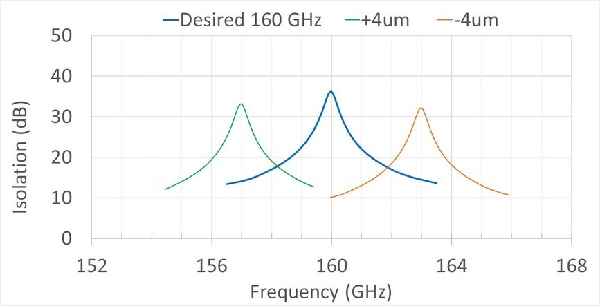
Figure 2 – The blue curve shows measured data for a circulator properly tuned to 160 GHz. The orange and green curves show the impact of the ferrite dimension being off by ± 4 μm.
New Hybrid Circulator
Micro Harmonics recently developed a new type of circulator which we named a hybrid circulator. The hybrid circulator comprises a Faraday rotator and an orthomode transducer (OMT) [1]. The theory of operation of the hybrid circulator is different to that of the Y-junction. The hybrid circulator is inherently broadband because both the Faraday rotator and the OMT are themselves broadband. Micro Harmonics developed the first hybrid circulator prototype through funding under a NASA research grant. That prototype successfully covered the band from 150-190 GHz with more than 20 dB isolation and less than 1 dB insertion loss.
The fractional bandwidth of the hybrid circulator (24%) is an order of magnitude greater than a Y-junction circulator (2%) operating in that frequency range. Subsequently, a full line of hybrid circulators was developed in every standard waveguide band from 50 GHz to 330 GHz, all with 24% fractional bandwidths. More information on the hybrid circulators is available at the Micro Harmonics website.
The 24% bandwidth limitation is not fundamental but is caused by excitation of the higher order TE11 and TM11 modes in the common mode waveguide in the asymmetric T-junction OMT used in the design. Micro Harmonics recently redesigned the hybrid circulator using a symmetric OMT to achieve greater than 40% fractional bandwidths covering full rectangular waveguide bands.
The new fullband hybrid circulators have not yet been tested, but the HFSS models give good results. A prototype for the WR-6.5 band is currently being fabricated and will be released to the market once the performance is validated. Figure 3 shows a comparison of the measured 20 dB bandwidths for Y-junction circulators as compared to our current line of 24% hybrid circulators. Estimated bandwidths for the newest hybrid circulators (gen 2) are also shown in the graph.
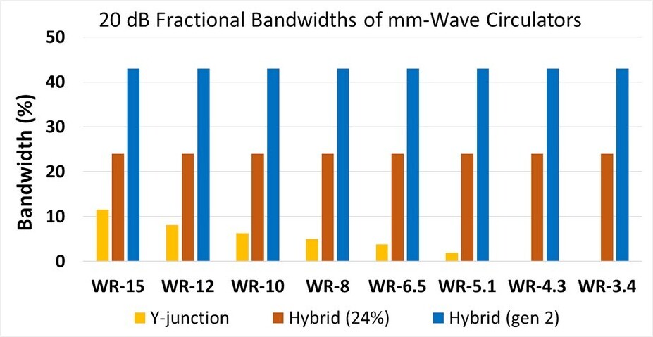
Figure 3 – HFSS simulation data for a hybrid circulator covering the entire WR-6.5 band 110-170 GHz.
The insertion loss of the hybrid circulators is comparable to Y-junction devices. The measured average insertion loss of the existing line of 24% hybrid circulators is near 0.6 dB in the WR-15 through WR-10 bands, 0.8 dB in the WR-8 band, 1.0 dB in the WR-6.5 band, 1.6 dB in the WR-4.3 band, and 2.6 dB in the WR-3.4 band. Port reflections are generally less than -16 dB. The hybrid circulator is an enabling technology in the higher MMW bands where broadband circulator functionality was not previously available. The hybrid circulator is patent pending. Please contact Micro Harmonics for more information.
References
[1] D. W. Porterfield, “Broadband Millimeter-Wave Hybrid Circulators,” IEEE Trans. Microw. Theory Techn., vol. 71, no. 8, pp. 3501-3507, Aug. 2023.