
Fullband mm-Wave Circulators Are on the Horizon
Diving into Revolutionary Circulator Developments
Circulators are useful in transmit/receive systems, isolating a transmitter from a receiver while allowing them to share a common antenna. For more than 50 years the Y-junction circulator has been the primary implementation at mm-wave frequencies. Commercial Y-junction circulators with full waveguide band operation are available up to 40 GHz, although the isolation is generally less than 16 dB. Above 50 GHz the bandwidth is severely limited and there are few vendors. The narrow bandwidth makes them unsuitable for many systems, forcing undesirable bandwidth limitations. And it can be difficult to tune the Y-junction devices at the higher mm-wave frequencies. For example, a ±4 μm variation in the diameter of a ferrite core can alter the center frequency of a 160 GHz Y-junction circulator by more than ±3 GHz, a huge problem since the 20 dB bandwidth is less than 3 GHz.
Hybrid Circulators
Micro Harmonics Corporation (MHC) recently developed a new type of circulator which they call a hybrid circulator [1]. The patent pending hybrid circulator comprises a Faraday rotator and an orthomode transducer (OMT). Since both the Faraday rotator and OMT are broadband devices, the hybrid circulator is also broadband. The first prototypes were developed to cover the 150-190 GHz band in WR-5.1. Figure 1 shows measured isolation for both the hybrid circulator and a Y-junction circulator. The hybrid circulator bandwidth (24%) is an order of magnitude greater than the Y-junction (2%).
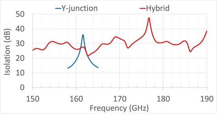
Figure 1: Measured isolation of a Y-junction circulator and a hybrid circulator in the WR-5.1 band.
Micro Harmonics has released a new line of these components in every standard rectangular waveguide band from WR-15 (50-75 GHz) through WR-3.4 (220-330 GHz). Figure 2 shows measured bandwidth for the new hybrid circulators as well as measured bandwidth for Y-junction circulators. It should be stressed that the 24% hybrid circulator bandwidth is not a fundamental limit. In the current design, the hybrid circulator uses an asymmetric OMT. An asymmetric OMT is used because it does not require internal pins or a septum and is easy to machine. But the asymmetry excites the higher order TE11 and TM11 modes which gives rise to the 24% bandwidth limitation.
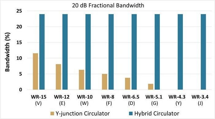
Figure 2: Measured 20 dB bandwidths of Y-junction circulators and hybrid circulators.
Although a remarkable achievement, the 24% fractional bandwidth of the hybrid circulator is still less than a standard rectangular waveguide band (40%). There are applications where operation over full rectangular waveguide bandwidths are required. In response to this need, a new version of the hybrid circulator was designed to work over the entire WR-6.5 band, 110-170 GHz. HFSS simulation data for the new full-band hybrid circulator are shown in Figure 3. According to the HFSS simulations models, isolation is greater than 20 dB across the band, insertion loss is around 2 dB and return loss is greater than 16 dB. The device is scheduled to be assembled and tested in the first quarter of 2024.
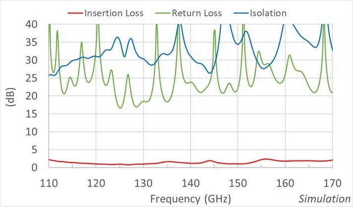
Figure 3 – HFSS simulation data for a hybrid circulator covering the entire WR-6.5 band 110-170 GHz.
Explore Micro Harmonics’ range beyond hybrid circulators, featuring mmw attenuators and mmw isolators for advanced technology applications. Feel free to reach out to Micro Harmonics at sales@mhc1.com if you have any questions.
References
[1] D. W. Porterfield, “Broadband Millimeter-Wave Hybrid Circulators,” IEEE Trans. on Microw. Theory and Tech., vol. 71, no. 8, pp. 3501-3507, Aug. 2023, doi: 10.1109/TMTT.2023.3239886.