
A mm-Wave Circulator with High Transmitter and Receiver Isolation (Part 1)
Circulators are used in transmit/receive systems to allow a transmitter and receiver to share a common antenna. A circulator schematic is shown in Figure 1, with typical connections for the transmitter (Tx), receiver (Rx), and antenna (Ant).
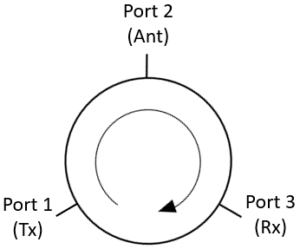
Figure 1 – Schematic for a circulator showing transmitter (Tx), antenna (Ant), and receiver (Rx) connections.
The most common circulator topology at mm-wave frequencies is the Y-junction. The Y-junction bandwidth degrades quickly as the frequency increases at the higher mm-wave frequencies, as indicated in Figure 2. The 20 dB bandwidth is defined as the bandwidth over which the isolation between adjacent ports is greater than 20 dB.
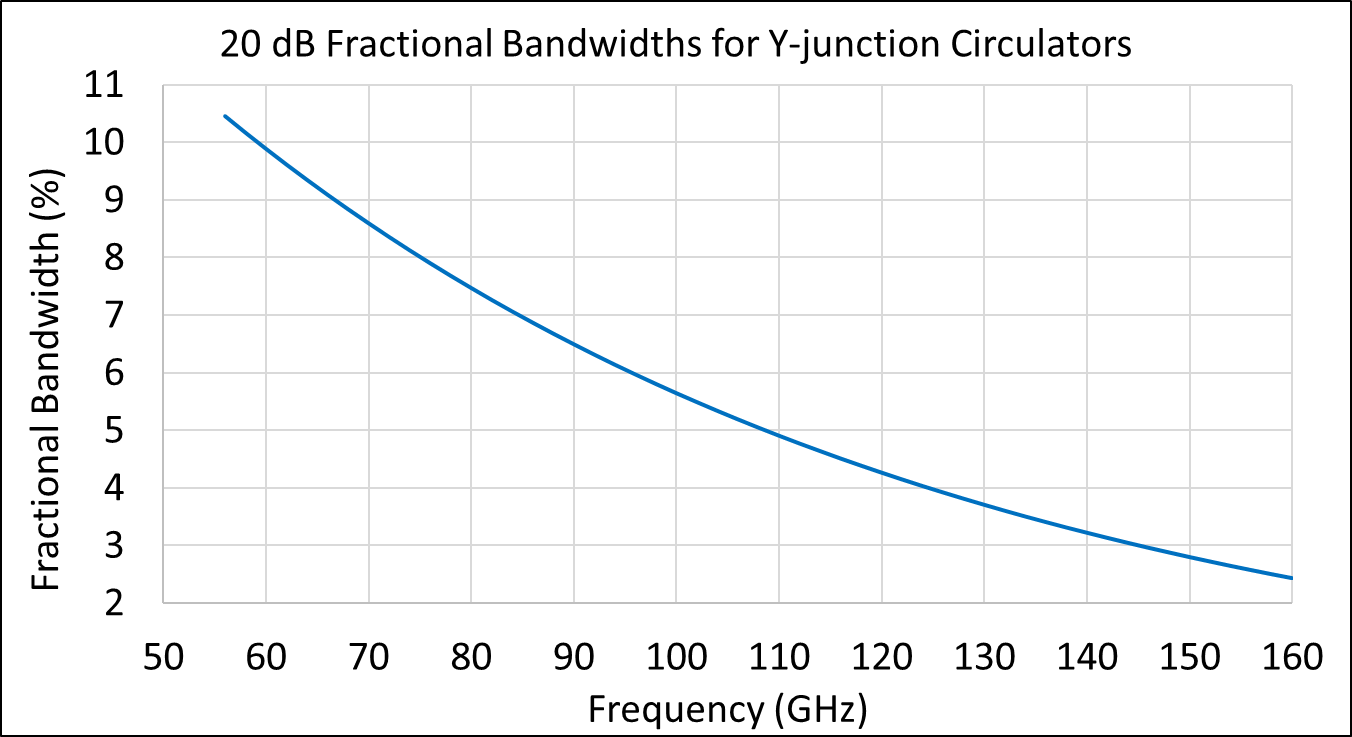
Figure 2 – The graph shows 20 dB bandwidths for Y-junction circulators. The data are from a combination of HFSS simulations and RF test measurements.
Figure 3 shows simulation data for a Y-junction circulator optimized to have more than 20 dB isolation across a band centered at 95 GHz. The isolation is greater than 20 dB across the band from 92-98 GHz, with a fractional bandwidth of 6%. This agrees with the data in Figure 2.
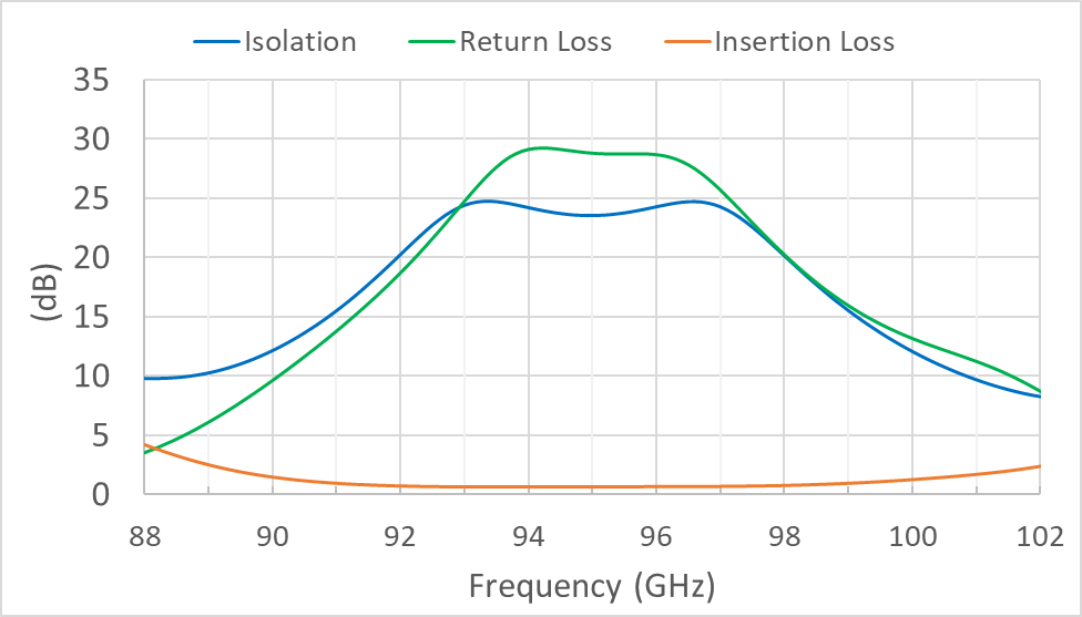
Figure 3 – HFSS simulation data for a Y-junction circulator. The model was optimized to have more than 20 dB isolation across a band centered at 95 GHz.
Triple Junction Circulator
Multiple Y-junction circulators can be combined in a single waveguide block to achieve higher isolation levels. A schematic of a triple junction circulator is shown below. The three circulators are designated “A”, “B”, and “C”.
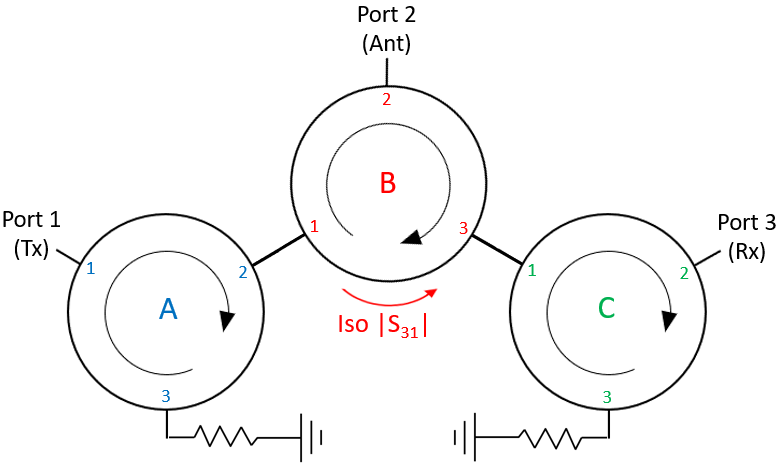
Figure 4 – A triple junction circulator schematic showing Tx, Ant, and Rx connections.
Circulators “A” and “C” function as isolators since their third ports are terminated with matched loads. The triple junction schematic can be redrawn, as shown in Figure 5.
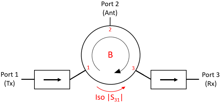
Figure 5 – The triple junction circulator schematic redrawn with two of the Y-junctions replaced with isolators.
In the triple junction circulator, an RF signal entering the antenna port is blocked from reaching the transmitter by the isolation |S12| in Y-junction circulator “B” and isolation |S12| from Y-junction circulator “A”. These two isolation paths are in series. Figure 3 shows a Y-junction circulator with more than 20 dB isolation across the 92-98 GHz band. Using a triple junction configuration, we might then expect to achieve close to 40 dB isolation of the transmitter from a signal entering the antenna port.
Since high-power transmitters can be sensitive to even small signals entering the output port, the triple junction offers a distinct advantage. You can achieve a similar result by attaching an isolator to a single Y-junction circulator. However, the triple junction configuration is more compact and less expensive to fabricate.
Another concern in many transmit/receive systems is the unwanted coupling of a high-power transmit signal (Tx) to a sensitive receiver (Rx). In this case, the triple junction offers no advantage over the single junction. In both cases, a single isolation path, |S31|, blocks the transmit signal from reaching the receiver. Regardless of how many junctions are used, a multi-junction circulator can only have a single isolation path protecting the receiver from the transmit signal. The isolation is always provided by the Y-junction connected to the antenna.
A leading manufacturer advertises a triple junction circulator with more than 35 dB isolation over 92-98 GHz. However, on closer inspection, we find that the |S31| isolation of the receiver from the transmitter is actually less than 20 dB. This is simply a fundamental limitation in the Y-junction technology.
The Hybrid Circulator
The good news is that Micro Harmonics recently developed a new type of mm-wave circulator technology that does not depend on the Y-junction. The new hybrid circulator comprises a Faraday rotator and an orthomode transducer which are combined to produce the circulator function. The hybrid circulator has a completely different theory of operation and is inherently broadband.
Micro Harmonics has designed and marketed hybrid circulators with 24% fractional bandwidths in every standard waveguide band from WR-15 (50-75 GHz) to WR-3.4 (220-330 GHz). A full-band version of the hybrid circulator in D-band (110-170 GHz) was recently released, where the isolation between ports was 20 dB across the full waveguide band.
Micro Harmonics is now experimenting with versions of the hybrid circulator that are optimized to achieve high isolation between the transmitter and receiver (|S31|). The initial design effort targets the 92-98 GHz radar band. This is also a band where commercial triple junction isolators are available for comparison.
Isolation data from the most recent HFSS models are shown in Figure 6. The isolation of the receiver from the transmitter signal, |S31|, is more than 30 dB across the band from 90-100 GHz, more than 35 dB across the band from 92-98 GHz, and 40 dB across the band from 93-97 GHz. The other two isolation paths |S12| and |S23| are greater than 27 dB across the 90-100 GHz band. An isolator can be attached to port 1 to achieve |S12| > 50 dB.
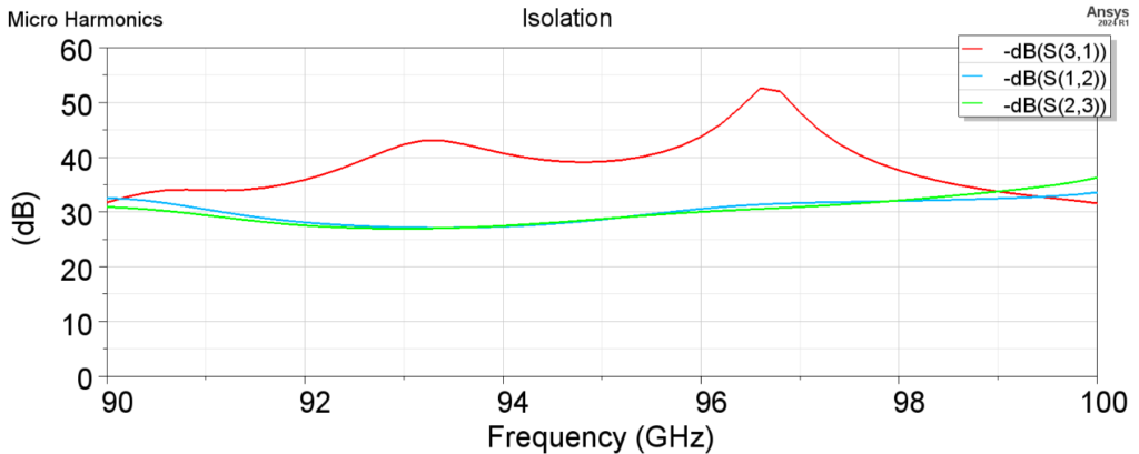
Figure 6 – HFSS simulation data of a hybrid circulator designed for maximum |S31| isolation at 92-98 GHz.
The Future of mm-Wave Circulators: Embracing Hybrid Solutions
Y-junctions have been the dominant circulator technology at mm-wave frequencies for more than 50 years. However, the Y-junction bandwidth degrades at the higher mm-wave frequencies. Y-junctions can achieve 20 dB isolation over the band 92-98 GHz. A triple junction circulator can offer more than 35 dB isolation of the transmitter from a signal entering the antenna, which can be very useful for some high-power transmitters that can be sensitive to signals entering their output ports. However, the receiver is isolated from the high-power transmitter signal at only the 20 dB level, regardless of whether a single or triple junction circulator is used.
The new hybrid circulator technology from Micro Harmonics does not rely on a Y-junction. The hybrid circulator is inherently broadband. A hybrid circulator covering all of the D-band (110-170 GHz) with more than 20 dB isolation across the band has been demonstrated and released for sale. New versions of the hybrid circulator are being designed to maximize the isolation between the sensitive receiver and the high-power transmitter ports. HFSS simulations now indicate more than 35 dB isolation is possible in the 92-98 GHz band. This is more than 15 dB greater than the isolation offered by the triple junction over the same band. Micro Harmonics has extensive experience in the design of hybrid circulators and has a high degree of confidence in the models. The hybrid circulator is protected under US patent 12034196. A patent is pending in Europe. If you have any questions regarding our isolators, attenuators, orthomode transducers, or circulators, feel free to contact us!
Continue reading: A mm-Wave Circulator with High Transmitter and Receiver Isolation (Part 2).