
Micro Harmonics offers a complete line of Faraday rotation isolators covering 25-400 GHz in every standard waveguide band from WR-28 through WR‑2.8. These isolators exhibit state-of-the-art performance in terms of low-insertion loss, broad-bandwidth, low port reflections, and the highest frequency coverage in the industry. They are the most advanced isolators on the market today.
“The compact size, extremely low insertion loss, and the wide bandwidth have allowed us to use isolators in a wider variety of our systems than was previously possible and have led to significant improvements in key system performance metrics such as source power and sensitivity.”
Jeffrey Hesler, Ph.D.
CTO, Virginia Diodes
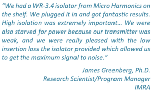
“They had an isolator with the single most important parameter I needed, low insertion loss. They were ultimately able to select one with just 1.2 dB loss at 240 GHz, which is pretty phenomenal.”
Curt Dunnam, Director of Operations
ACERT National Biomedical Center at Cornell
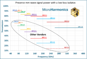
The graph below shows the insertion loss of our isolators as compared to other vendors. The insertion loss of our WR-3.4 isolator is only 2 dB. Don’t waste valuable mm-wave signal power by using an isolator with high insertion loss. Join the many companies who are using our isolators in their systems and seeing tangible improvements in system performance.
| Model | Flange (EIA) |
Band (GHz) |
Insertion Loss (dB, typ) |
Isolation (dB, typ) |
Max Power (dBm | W)* |
|---|---|---|---|---|---|
| FR280 | WR-28 | 26 – 40 | 0.5 | 23 | 37 | 5.0 |
| FR188 | WR-19 | 40 – 60 | 0.5 | 20 | 36 | 4.3 |
| FR148 | WR-15 | 50 – 75 | 0.6 | 23 | 36 | 3.8 |
| FR122 | WR-12 | 60 – 90 | 0.5 | 20 | 35 | 3.5 |
| FR100 | WR-10 | 75 – 110 | 0.6 | 25 | 35 | 2.9 |
| FR090 | WR-9 | 82 – 122 | 0.9 | 21 | 34 | 2.7 |
| FR080 | WR-8 | 90 – 140 | 0.8 | 24 | 34 | 2.4 |
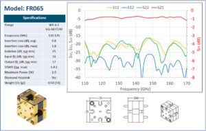
| FR065 | WR-6.5 | 110 – 170 | 0.8 | 25 | 33 | 1.9 |
| FR051 | WR-5.1 | 140 – 220 | 1.1 | 22 | 31 | 1.3 |
| FR043 | WR-4.3 | 170 – 260 | 1.3 | 22 | 30 | 1.0 |
| FR034 | WR-3.4 | 220 – 330 | 1.8 | 23 | 28 | 0.6 |
| FR028 | WR-2.8 | 260 – 400 | 2.7 | 21 | 26 | 0.4 |
Distinctives
- Lowest insertion loss
- Highest power rating
- Full band test data
- Direct engineering support
Applications
- Impedence matching
- Protection from reflected power
- Measurement & instrumentation
- Sub-assemblies
- Laboratory measurement & test equipment
- Broadband systems
A typical specification sheet is shown below. Every component is thoroughly RF tested and the data for each individual component is shared with the customer. Our isolators employ a unique diamond heatsink for improved power handling and reliability. Our isolators are resistant to stray magnetic fields. We use anti-cocking waveguide flanges. All our products are fully guaranteed. We design and manufacture all our products in the United States.
Faraday Rotation Isolators – Sample Test Data
FR122: 60-90 GHz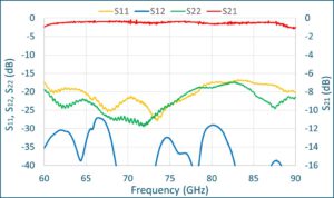 |
FR100: 75-110 GHz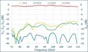 |
FR80: 90-140 GHz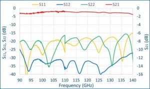 |
FR65: 110-170 GHz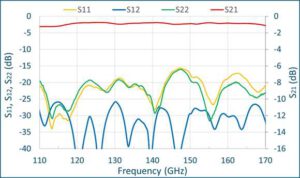 |
FR51: 140-220 GHz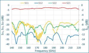 |
FR43: 170-260 GHz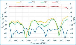 |
FR34: 220-330 GHz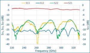 |
 |
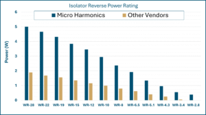
Isolator Power Ratings – In a Faraday rotation isolator, reverse power is absorbed in a resistive layer and converted to heat energy. In isolators sold by other vendors, the resistive layer can get hot because it is thermally isolated. But Micro Harmonics isolators employ a diamond disc that provides an excellent path to conduct heat from the resistive layer to the metal block. The graph below shows the maximum reverse power ratings of our isolators and the average of other vendors. The Micro Harmonics power ratings are conservative to ensure low temperatures and long life.
Highest Power Rating
Micro Harmonics Isolators are Insensitive to Stray Magnetic Fields – Have you seen the label on the legacy isolator that warns you to keep it away from magnetic fields? You will not find that label on a Micro Harmonics isolator because our isolators are highly resistant to external magnetic fields. The legacy isolators use a highly tuned magnetic field that is easily perturbed by even a small external magnetic field. This causes under- or over-rotation of the signal and severe performance degradation. Micro Harmonics isolators use a highly saturated magnetic bias field which makes them insensitive to stray magnetic fields. The phenomenon is explained in more detail in an article published in the April 2021 edition of the Microwave Journal.