
This article appears in the April 2021 edition of the Microwave Journal.
David W. Porterfield, Jr, Ph.D., Micro Harmonics Corporation
Abstract
Faraday rotation isolators employ magnetically biased ferrite rods to rotate the polarization of an RF signal and are thus susceptible to stray magnetic fields. Stray magnetic fields are defined as those arising from sources external to the isolator and are not magnetic fields generated by the internal magnets used to bias the ferrite. The offending stray fields can arise from other nearby ferrite components but are also common in a variety of mm-wave experiments like dynamic nuclear polarization [1], particle accelerators [2] and tokamak fusion reactors [3]. Stray magnetic fields can in principle alter the magnetic bias point in the ferrite and cause under- or over-rotation of the RF signal. The end result is increased insertion loss and decreased isolation. Test results described in this paper will demonstrate that the traditional style isolators sold commercially over the past 50 years are highly susceptible to low level stray magnetic fields. Even in relatively weak stray fields, the insertion loss can exceed 30 dB rendering the device completely unusable. In contrast, the newer magnetically saturated type isolators, such as those offered by Micro Harmonics, function remarkably well in stray fields up to and exceeding 250 Oe.
Introduction
Isolators are non-reciprocal devices, passing EM signals in one direction and absorbing them in the reverse direction. They are primarily used to suppress standing waves that arise from signal reflections caused by impedance mismatches between highly-tuned components in microwave and millimeter-wave (MMW) systems. Standing waves limit system bandwidth and cause dips or even nulls in the final output. The standing waves can be mitigated by inserting isolators between mismatched components resulting in a smoother frequency response and improved bandwidth.
The isolator topology most frequently used at MMW frequencies is the Faraday rotation type first described by Barnes in 1961 [4]. These isolators employ a ceramic cone to couple a TE10 rectangular waveguide mode to a TE11 mode in a cylindrical ferrite rod. The signal polarization is rotated by 45° as it passes through the ferrite rod and is then coupled into an output waveguide via a second ceramic cone.
 |
| Figure 1 – Sketch showing the waveguides, ceramic cones and ferrite rod in a Faraday rotation isolator. |
 |
| Figure 2 – Rotation of the forward and reverse travelling signals as they pass through the ferrite rod. |
Figure 1 shows the layout of the waveguides, ceramic cones and ferrite rod in a typical isolator. The black arrows at the center of the input and output waveguides indicate the polarization of the primary TE10 waveguide mode. The input and output waveguides are canted at 45° with respect to each other. The ferrite rod spans the gap between the waveguides and has a diameter roughly equal to the waveguide height. Each cone has a resistive layer that bisects the central axis. The resistive layers are oriented such that they are normal to the TE10 mode polarization in their respective waveguides.
Figure 2 shows the orientation of the polarization vector of the electric field for the forward and reverse travelling signals. Both signals rotate in the same direction (CCW for the purpose of this illustration). The forward travelling signal is normal to the resistive layers in both cones, minimizing loss and signal attenuation. The polarization vector of the reverse travelling signal is aligned with the resistive layer in the input waveguide causing the signal to be absorbed.
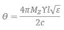
The rotation angle, θ, of the signal as it passes through the ferrite rod is directly proportional to the ferrite magnetization, 4πMZ, and the ferrite length, l, as shown in equation 1.
 |
(1) |
Where,
- 4πMZ is the axial magnetization
- ϒ is the gyromagnetic ratio,

- l is the ferrite length
- c is the speed of light
- ? is the ferrite dielectric constant
An external magnetic field is used to align magnetic dipoles in the ferrite giving rise to the desired axial magnetization, 4πMZ. Rare earth magnets are often used, typically neodymium (Nd2Fe14B) or samarium cobalt (SmCo5 or Sm2Co17). As the magnetic bias field increases, additional dipoles are aligned and the magnetization, 4πMZ, increases until reaching a point of saturation denoted as the saturation magnetization, 4πMS, beyond which further increases in the applied magnetic field have little effect. The magnitude of the saturation magnetization is a material dependent property and varies in the range 300-5000 gauss for most commercial ferrites. Ferrite material with 4πMS = 5000 gauss [5] is typically used in MMW isolators. The saturation magnetization is temperature dependent, following a modified Bloch law and reaching a maximum value at absolute zero (0 K) since it is easier to align magnetic dipoles at lower kinetic energy levels.
 |
| Figure 3 – Angular momentum and spin magnetic dipole moment vectors. |
The dipoles precess around the magnetic bias field vector as shown in the graphic in Figure 3. As an EM signal passes through the ferrite, the fields interact with the dipole moments. Linearly polarized waves, like those passing through the isolator, can be decomposed into left-hand circularly polarized (LHCP) and right-hand circularly polarized (RHCP) waves. The interaction with the precessing dipole moments yields disparate propagation constants for the RHCP and LHCP waves. The difference in the propagation constants arises because one of the components (RHCP or LHCP) opposes the dipole precession and the other coincides with it. As a result, a phase shift occurs between the RHCP and LHCP waves as they propagate through the ferrite. This gives rise to the rotation of the linearly polarized signal. More in-depth discussions on Faraday rotation are given by Pozar [6], Lax et. al [7] and Balanis [8].
 |
| Figure 4 – (a) Saturated and (b) traditional non-saturated WR-10 Faraday rotation isolators. |
Faraday rotation isolators can be classified into two basic categories: 1) magnetically saturated and 2) non-saturated. The saturated type is shown in Figure 4 (a). The non-saturated type is shown in Figure 4 (b). They can usually, but not always, be identified by their size and shape. Saturated isolators are smaller and do not have a magnetic sheath. The traditional non-saturated isolators are typically much larger and most have a hollow cylindrical magnetic sheath around the center section.
 |
| Figure 5 – Canted magnet in traditional isolator. |
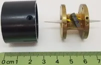
The photograph in Figure 5 shows a traditional non-saturating Faraday rotation isolator with the magnetic sheath and waveguides removed. The magnetic bias field is adjusted by rotating the magnet off axis until maximum isolation is achieved and then locking down the magnet with an epoxy. The long ferrite rod used in the non-saturating isolators is lossy at MMW frequencies leading to high insertion loss, but the ability to fine tune the rotation while testing in-situ is a powerful tool. Saturated isolators use a much shorter ferrite rod and a saturating magnetic bias field to achieve the required 45° of rotation. They are thus much smaller than the traditional isolator and have much lower insertion loss.
Stray Magnetic Field Tests
 |
|---|
| Figure 6 – (a) Saturated isolator in normal stray field test. (b) Sketch of normal stray field test apparatus showing the direction of the magnetic field. (c) Traditional style non-saturated isolator in normal stray field test. |
 |
| Figure 7 – (a) Traditional style isolator in axial stray field test. (b) Saturated isolator in axial stray field test. (c) Hall probe calibration of axial field magnetic coil. |
Laboratory tests were conducted in W-band (75-110 GHz) to determine the effects of stray magnetic fields. Two isolators were tested, one made by Micro Harmonics (saturated type) and a traditional style isolator made by another vendor (unsaturated type). Since the traditional style isolators have similar construction regardless of the manufacturer, the tested isolator is thought to be representative of its entire class. The tests were conducted using a Keysight N5222B PNA (vector network analyzer) and a pair of VDI W-band frequency extenders. The isolators were subjected both to normal and axial stray magnetic fields. Normal stray fields are oriented at a 90° angle to the magnetic bias field and axial stray fields are parallel to the bias field. The test apparatus used to produce normal stray magnetic fields is shown in Figure 6. The maximum field produced by the apparatus was measured to be ± 65 Oe.
A magnetic coil was used to produce axial stray magnetic fields as shown in Figure 7. The coil has 787 turns of 24 AWG magnet wire, an inner diameter of 38 mm and a length of 25 mm. The maximum axial field was measured at more than ± 260 Oe at the coil center. Both the normal and axial stray fields were calibrated using Hall effect sensors. However, magnetic materials used in the isolators may perturb the stray field intensity at the ferrite location when the isolators are inserted into the test apparatus.
 |
|---|
| Figure 8 – Test data for the saturated (red) and traditional style unsaturated isolators (blue) under normal (orthogonal) stray magnetic fields. The test data are taken at the W-band center frequency 92.5 GHz. |
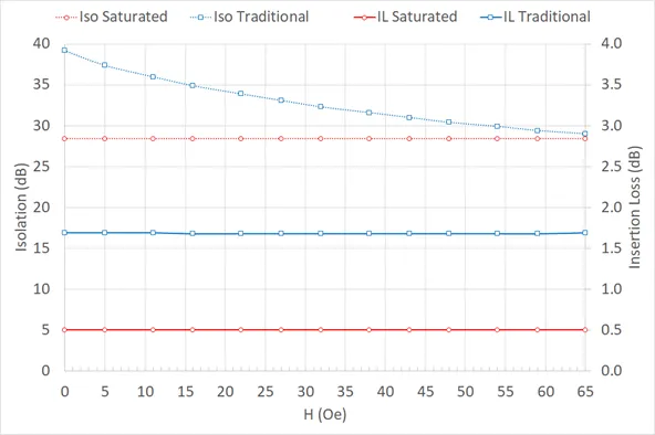
Normal (orthogonal) Stray Magnetic Field Tests
Full two port s-parameter data were recorded over 75-110 GHz as the calibrated normal stray magnetic field was varied. For simplicity, only data at the band center (92.5 GHz) is shown. The insertion loss (IL) and isolation (Iso) data for the two isolators are shown in Figure 8 for the case of normal stray magnetic field ranging from 0 to 65 Oe. The insertion loss of the saturated isolator remained nearly constant at 0.5 dB. The insertion loss of the traditional isolator also remained constant at 1.7 dB. There was no change in the isolation of the saturated isolator which remained constant at 28 dB. The isolation of the traditional style unsaturated isolator dropped from 39 dB to 29 dB, a relatively minor effect.
The data indicate that both isolators perform well under orthogonal stray magnetic fields. The magnetic sheath used in the traditional isolator efficiently diverts the normal stray magnetic field around the isolator body and away from the ferrite. The strong magnetic bias field used in the saturated isolator keeps the magnetic dipoles aligned in the presence of the normal stray magnetic field.
 |
|---|
| Figure 9 – Measured insertion loss (IL) and isolation (Iso) for the saturated (red) and traditional style isolators (blue) under axial stray magnetic fields. The test data are taken at the center of W-band, 92.5 GHz. |
Axial Stray Magnetic Field Tests
The test results for the axial stray magnetic fields are shown in Figure 9. The insertion loss and isolation of the saturated isolator are indicated by the red curves. The data indicate that the saturated isolator is largely unaffected by the axial stray magnetic fields. The insertion loss remains constant at 0.5 dB when subjected to stray axial magnetic fields between ‑220 Oe and +220 Oe. The isolation drops from 32 dB at -220 Oe to 25 dB at +220 Oe, indicating that the ferrite rod is slightly too long for peak performance.
The insertion loss and isolation of the traditional isolator are indicated by the blue curves. In this case, the isolation and insertion loss vary rapidly as a function of the axial stray magnetic field. With no stray field (H=0), the isolation was 30 dB and the insertion loss 1.7 dB. But when the stray axial field was increased by ± 38 Oe, both the insertion loss and isolation were 4.7 dB and the traditional style isolator degenerated to a bi-directional attenuator.
At a magnetic field strength of 80 Oe, the isolation and insertion loss values were reversed. The traditional style isolator once again behaved as an isolator but in the reverse direction. The magnetic sheath is clearly ineffective against axial stray fields. This is not surprising since the sheath has the form of a hollow cylinder with an inner diameter near 25 mm, far from the ferrite rod.
Analysis
The extrema in the data and the points where the isolation and insertion loss curves cross correspond to changes in the signal rotation of N*45°, where N is an integer having the range -5 to +3 and inclusive of 0. Figure 10 shows the cross-section of the transition region between the ferrite rod and the rectangular waveguides. The ferrite is indicated by a shaded circle and the orientation of the resistive layer is shown as a dashed line. Since the dipole precession is fixed by the magnetic bias field, both the forward and reverse travelling signals rotate in the counter-clockwise (CCW) direction as they pass through the ferrite rod. This is the basis for the non-reciprocal behavior of the Faraday rotation isolator. In the absence of a stray magnetic field, the signals rotate 45° CCW as they make a single pass through the ferrite. The forward travelling signal impinges on the output waveguide with the polarization aligned to the TE10 mode and is coupled to the output waveguide. The reverse travelling signal impinges on the input waveguide with the polarization aligned to the resistive layer in the input cone and is absorbed. This is the normal operating condition.
| Figure 10 – Polarizations of the forward and reverse signals after a single pass through the ferrite rod. |
If an axial stray magnetic field is applied with sufficient magnitude to double the ferrite magnetization, both the forward and reverse travelling signals undergo an additional 45° of rotation (90° total). The respective signal polarizations are indicated as 90° in Figure 10. Both the forward and reverse travelling signals now have equal vector components aligned to the resistive layer and the TE10 mode. Half of the signal power (3 dB) is absorbed in the resistive layer and half couples to the TE10 mode. Since the 3 dB split occurs at both the input and output waveguides at exactly the same magnetic bias condition, the insertion loss and isolation have the same value (|S21| = |S12|). The actual measured values are 4.7 dB rather than 3 dB due to an additional 1.7 dB loss in the ferrite rod.
If the stray magnetic field is further increased so that the rotation increases another 45° (135° total), the reverse travelling signal polarization is aligned to the TE10 mode in the input waveguide and the forward travelling signal is aligned to the resistive layer located in the cone in the output waveguide. The signal polarizations are shown labeled as 135° in Figure 10. The isolator now works in the reverse direction, absorbing forward travelling signals and passing reverse travelling signals. Reversing the polarity of the axial stray magnetic field causes the same series of events to occur with the signal rotation now in the clockwise direction.
The measured data in Figure 9 give the value of the magnetic field, H, for the extrema and the crossings. As described, these are the points at which the rotation is an integer value of 45°. The ferrite rods used in traditional style isolators are typically 6 mm long as reported by Erickson [9]. Using the equation for rotation (eq. 1) with θ = 45° and l = 6 mm, yields a magnetization of 4pMZ = 1258 gauss. Each 45° rotation step therefore corresponds to a magnetization increment of 1258 gauss.
 |
|---|
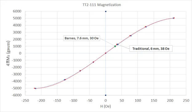
| Figure 11 – Measured magnetization curves for ferrite with 4pMS = 5000 gauss [5]. |
The resulting plots of magnetization, 4pMZ, versus magnetic field, H, are shown in Figure 11. Two curves are shown because of a small hysteresis observed in the data. The red curve was obtained by starting at the highest possible negative field (about -260 Oe) and reducing the magnitude. The red data points were thus taken in order from left to right on the graph. The blue data points were taken in order from right to left on the graph. The blue and red data points represent the crossings and peaks in our measured data. The dashed lines are fourth order polynomial curve fits to the data.
The plotted curves in Figure 11 reach saturation near 5000 gauss. Negative values of 4πMZ are used to denote reversal of the magnetic field polarization. Additional interim data points may be obtained by constructing an isolator with a longer ferrite rod. The magnetic bias point of the traditional style isolator is indicated on the graph. The magnetic bias field used in the Micro Harmonics isolators has been measured at more than 700 Oe and therefore does not fit on the graph. At 700 Oe the bias point is hard into saturation where the slope of the magnetization curve, dMZ/dH, is near zero, which explains the saturated isolator’s insensitivity to stray magnetic fields.
Barnes [4] reported using a 7.6 mm length of ferrite rod with 4πMS = 5000 gauss and a magnetic field near 30 Oe. Using equation 1, the calculated magnetization required to rotate the signal by 45° is 990 gauss. This data point also falls on the measured magnetization curves in Figure 11.
Conclusion
Traditional style Faraday rotation isolators employing a magnetic sheath are highly sensitive to stray magnetic fields. The magnetic sheath gives good protection against stray magnetic fields that are orthogonal to the magnetic bias field but provides little or no protection against axial stray magnetic fields aligned parallel to the bias field. This is expected since the magnetic sheath has the form of a hollow cylinder with an inner diameter near 25 mm, far from the ferrite rod. Figure 11 shows that the magnetic bias point of the traditional isolator is on the steep part of the magnetization curve where small changes in the magnetic bias field, H, give rise to relatively large changes in the magnetization, 4πMZ. This in turn causes large changes in the signal rotation and results in severely degraded isolator performance. The long ferrite used in the traditional style unsaturated isolators also causes high insertion loss at the higher millimeter-wave frequencies. The insertion loss of the traditional isolator was measured to be 1.7 dB at 92.5 GHz.
In contrast, the magnetically saturated isolators are highly resistant to the effects of stray magnetic fields, both axial and orthogonal, even though the isolators do not employ a magnetic sheath. The resistance to stray magnetic fields arises from the fact that the ferrite is biased hard into saturation where the slope of the magnetization curve is near zero. Relatively large changes in the magnetic bias caused by stray magnetic fields have little effect on the magnetization. The saturated isolators also employ a much shorter ferrite rod which significantly reduces the insertion loss. The insertion loss of the Micro Harmonics isolator was measured to be 0.5 dB at 92.5 GHz.
Data from the axial stray magnetic field tests were used to construct a plot of magnetization, 4πMZ, versus applied magnetic field, H. The magnetic bias points of the traditional isolator and the isolator described by Barnes were plotted on the magnetization curve.
Acknowledgements
We would like to thank NASA JPL for their continued support of this work through research contracts NNX15CP37P, NNX16CP07C, 80NSSC18P2018 and 80NSSC19C0148.
References
[1] Qing Zhe Ni et al., “High Frequency Dynamic Nuclear Polarization,” Acc. Chem. Res. 2013, 46, 9, 1933–1941, Publication Date:April 18, 2013
[2] M. C. Downer, R. Zgadzaj, A. Debus, U. Schramm, and M. C. Kaluza, “Diagnostics for Plasma-Based Electron Accelerators,” Rev. Mod. Phys. 90, 035002, Aug. 8, 2018
[3] Hans-Jürgen Hartfuß and Thomas Geist, “Fusion Plasma Diagnostics with mm-Waves: An Introduction,” ISBN-13: 978-3527411054, Wiley-VCH; 1 edition, Nov. 4, 2013.
[4] C.E. Barnes, “Broad-band Isolators and Variable Attenuators for Millimeter Wavelengths,” IEEE Trans. Mic. Theory Tech., vol. 9, pp. 519-523, 1961.
[5] Ferrite TT2-111, Trans-Tech Corporation, Adamstown, MD.
[6] David Pozar, “Microwave Engineering,” Wiley.
[7] Benjamin Lax and Kenneth Button, “Microwave Ferrites and Ferrimagnetics,” McGraw Hill
[8] Constantine A. Balanis, “Advanced Engineering Electromagnetics,” Wiley; 2nd edition, 2012.
[9] N. R. Erickson, “Very Low Loss Wideband Isolators for mm-Wavelengths,” 2001 IEEE MTT-S Dig., pp. 1175-1178.