
Multipaction Analysis for Millimeter-Wave Isolators and Hybrid Circulators
Multipaction [1, 2] is a phenomenon occurring primarily in RF systems operating in a vacuum such as those found on space-based platforms. RF fields accelerate charged particles (electrons) which gain energy and collide with surfaces. If the impact energy is sufficient, additional electrons are released from the surface. The newly released electrons can, in turn, be accelerated by the RF fields and impact other surfaces. If there is sufficient power in the electromagnetic fields, a self-sustaining electron multiplication occurs which can lead to an avalanche condition. Multipaction can cause surface damage in conductors and dielectric materials as well as component and system failures.
Figure 1 gives a simplified illustration of multipaction using two parallel surfaces. The two surfaces could represent two opposing broad walls of a rectangular waveguide. A high-power RF signal is propagating in the region between the two surfaces and accelerating the electrons. A free electron accelerated by the RF fields strikes surface 1 (blue arrow) liberating two electrons from the surface (purple arrows). The two liberated electrons are accelerated by the RF fields and strike surface 2 liberating four electrons (green arrows) which then strike surface 1 liberating eight electrons (red arrows). On space-based platforms, the initial free electrons are typically released from one of the surfaces by high energy particles.
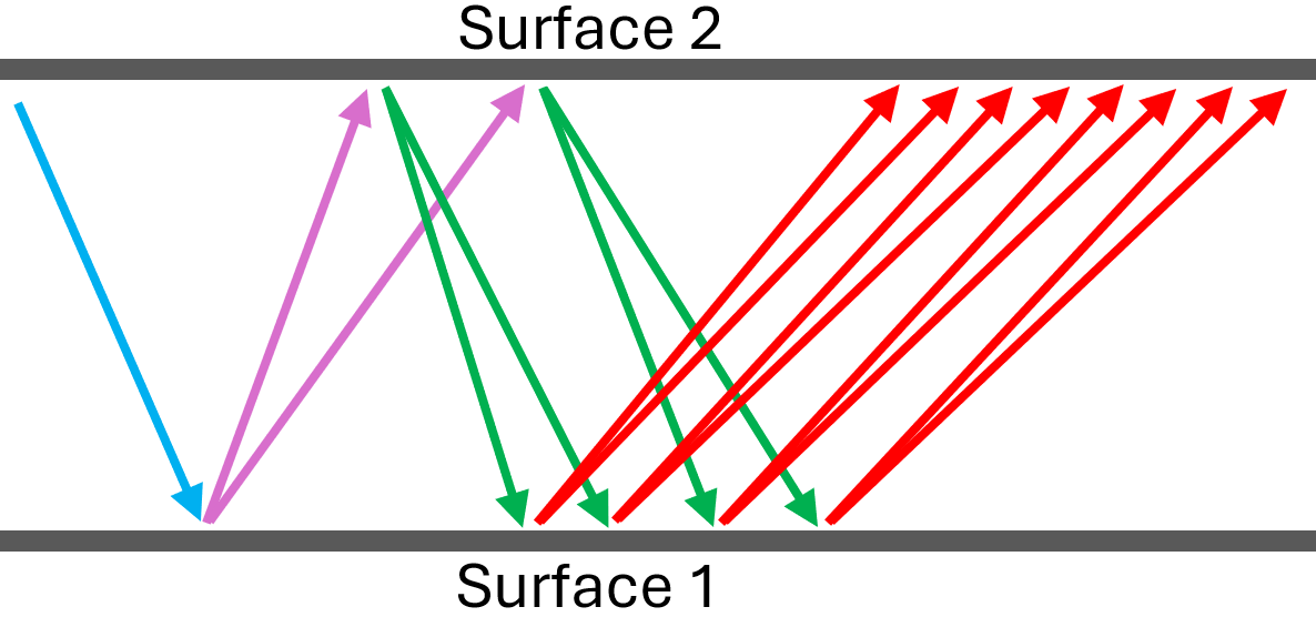
Figure 1 – Simplified illustration of multipaction between two parallel surfaces.
We present an analysis of the multipaction phenomenon in millimeter-wave (MMW) hybrid circulators [3]. The hybrid circulator comprises a Faraday rotator and an orthomode transducer (OMT). The Faraday rotator closely resembles the Faraday rotation isolators described by Barnes [4] and Erickson [5]. Thus, these findings are applicable to MMW Faraday rotation isolators as well as hybrid circulators. The analysis is done using the multipactor tool in HFSS [6]. The models are constructed in the WR-5.1 band 140-220 GHz.
Multipaction Analysis
The graphic in Figure 2 shows the functional parts of the hybrid circulator. The OMT is an asymmetric T-junction [7, 8] having three ports. The axial and lateral ports support a single TE10 mode. The common section supports two propagating modes (TE10 and TE01) having orthogonal polarizations. Signal polarization is rotated by 45° in a single pass through the Faraday rotator. The twist steps can be configured to realign the signal polarization to either the axial or lateral ports (the antenna port can be oriented in the same direction as the axial or lateral port).
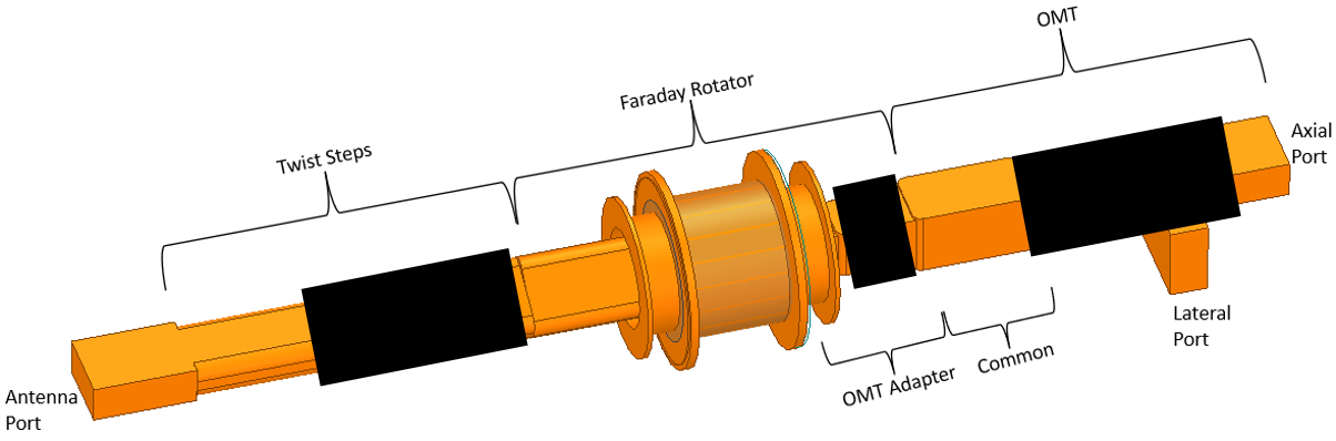
Figure 2 – Functional parts of the hybrid circulator. Some proprietary features are blacked out.
The hybrid circulator can be broken up into three parts to reduce the size and complexity of the multipaction models. The three models are 1) the OMT, 2) the Faraday rotator, and 3) the twist steps.
OMT
Secondary electron emission (SEE) boundaries are defined on all metal surfaces of the OMT. The HFSS SEE is based on an enhanced Vaughan model where the secondary yield curve falls on the low and high cutoff energies. SEE boundaries were not defined on the axial, lateral, or common ports. Charged particles striking the ports are absorbed. The interior region of the OMT was defined as a multipaction charge region and seeded with 500 charged particles.
Results of the multipaction analysis are shown in Figure 3. A single excitation of 1 W at 180 GHz was used on the axial port (there were no excitations on the lateral or common ports). For a single excitation of 1 W, the power multipliers indicated in the legend give the total RF power in watts. At an RF power of 40 kW the number of charged particles decreases from 500 to 30 after 10 ns. With an RF excitation of 50 kW, the charged particle count drops from 500 to near 100 after 10 ns.
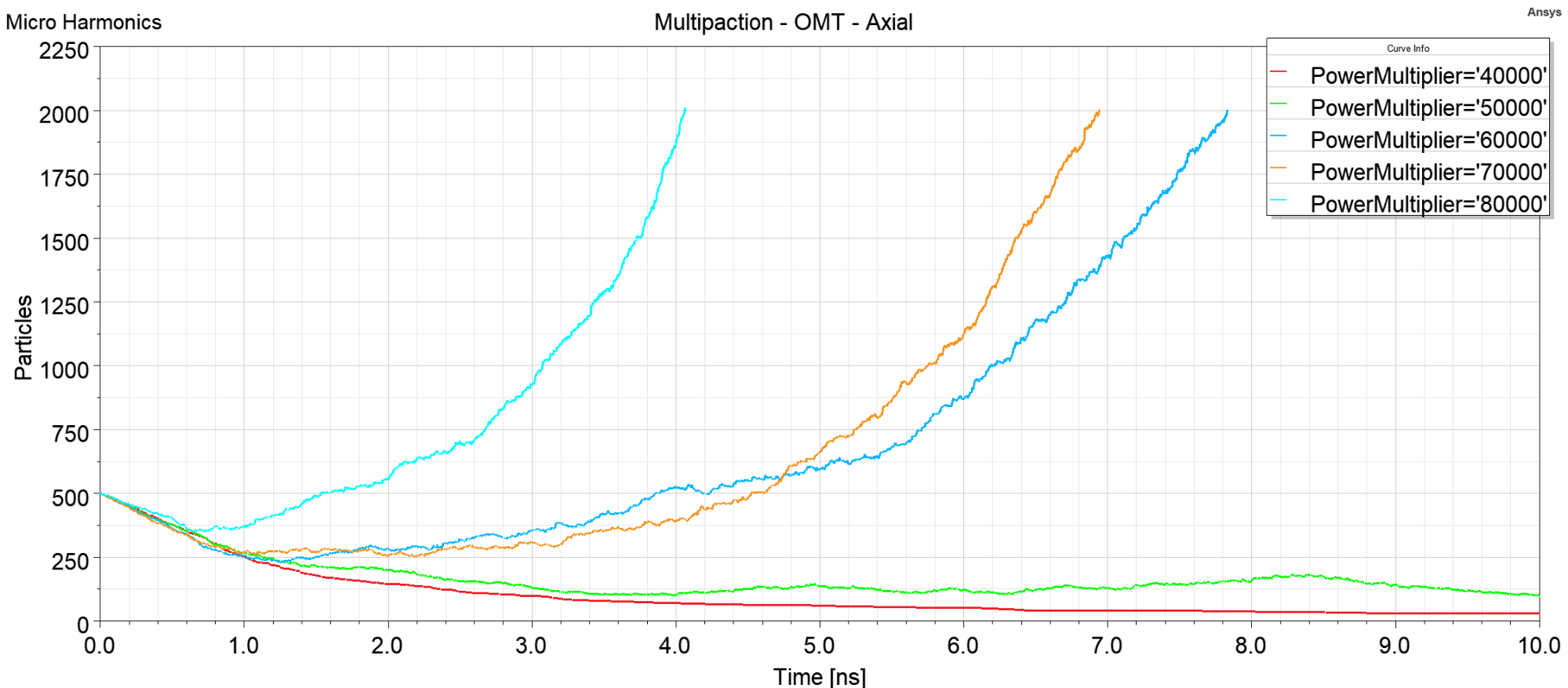
Figure 3 – Multipaction analysis for the WR-5.1 OMT. A single excitation at 180 GHz was used on the axial port. The power multipliers in the legend give the RF excitation power in W.
At 40-50 kW, there is no evidence of multipaction. Multipaction becomes evident at an excitation level of 60 kW where the charged particle count reaches 2000 after less than 8 ns. The maximum charged particle count was set to 2000 in order to reduce the solve time. At 70 kW excitation, the particle count reaches 2000 after less than 7 ns. At an RF excitation of 80 kW the particle count reaches 2000 after about 4 ns.
In our models, the entire interior of the OMT is uniformly seeded with charged particles. There is a high degree of isolation between the lateral and axial arms of the OMT, typically greater than 80 dB in the simulations. Therefore, the RF signal power in the lateral arm is very small. The charged particles in the lateral arm take much longer to move a sufficient distance to strike a conducting surface. This is evident by the fact that after 10 ns more than 30 particles remained out of the initial 500 seeded. Simulations were run with excitation on both orthogonal modes on the common port. HFSS adjusts the power in this case such that the power multiplier is the total combined power in both modes. The results of the simulation are shown in Figure 4.
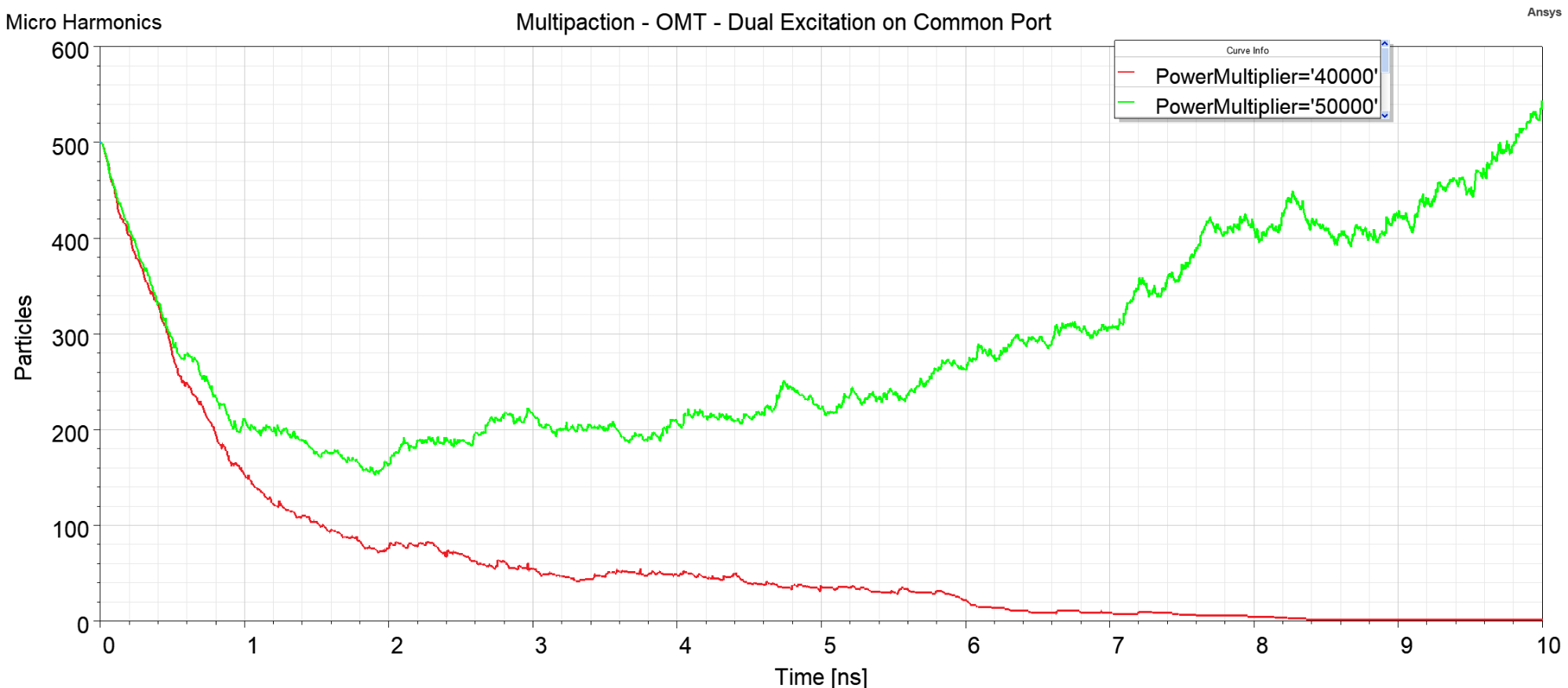
Figure 4 – Multipaction simulation where both orthogonal modes on the common mode port are excited. The power multiplier gives the total combined power for the two polarizations.
At 40 kW, the particle count drops to zero at 8.5 ns. With equally large RF signals traversing both the lateral and axial arms, the charged particle count reaches zero. Under 50 kW excitation the particle count increases to 540 at 10 ns, indicating multipaction. Multipaction was not evident at 50 kW when only the axial port was excited. The asymmetry in the OMT structure is likely the cause.
Another simulation was run using a single excitation on the lateral port (no excitation on the axial or common ports). The results of the simulation are shown in Figure 5. At RF excitation powers of 60 kW and lower, the particle count converges to 85 after 10 ns. The remaining particles are likely located in the axial arm which is isolated from the RF excitation. Multipaction is evident at RF excitations of 70 kW and higher.
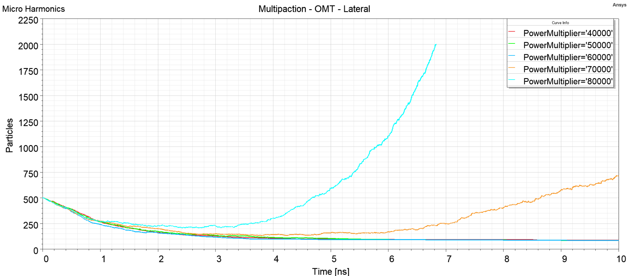
Figure 5 – Multipaction simulation with excitation on the lateral port (no RF excitation on the axial or common ports). The RF frequency is 180 GHz. Multipaction is evident at 70 kW.
In our simulations, the lowest RF excitation required for multipaction was 50 kW. This occurred in the case where dual mode RF excitation was used on the common port (see Figure 4). There are a lot of uncertainties and assumptions made in multipaction simulations, so it is common practice to derate the results. Based on our analysis and using a safety factor of 8, the multipaction rating for the OMT would be near 6 kW. In WR-5.1 (140-220 GHz) there are few sources capable of producing RF power levels near 6 kW. It is unlikely that the WR-5.1 hybrid circulator will be used at power levels much beyond 1-2 W.
Step Twist
RF signals are rotated by 45° in the Faraday rotator and the twist is used to realign the signal polarization to the other waveguide flanges. The results from the multipaction simulations on the twist step are shown in Figure 6. Multipaction occurs for power levels of 60 kW and higher.
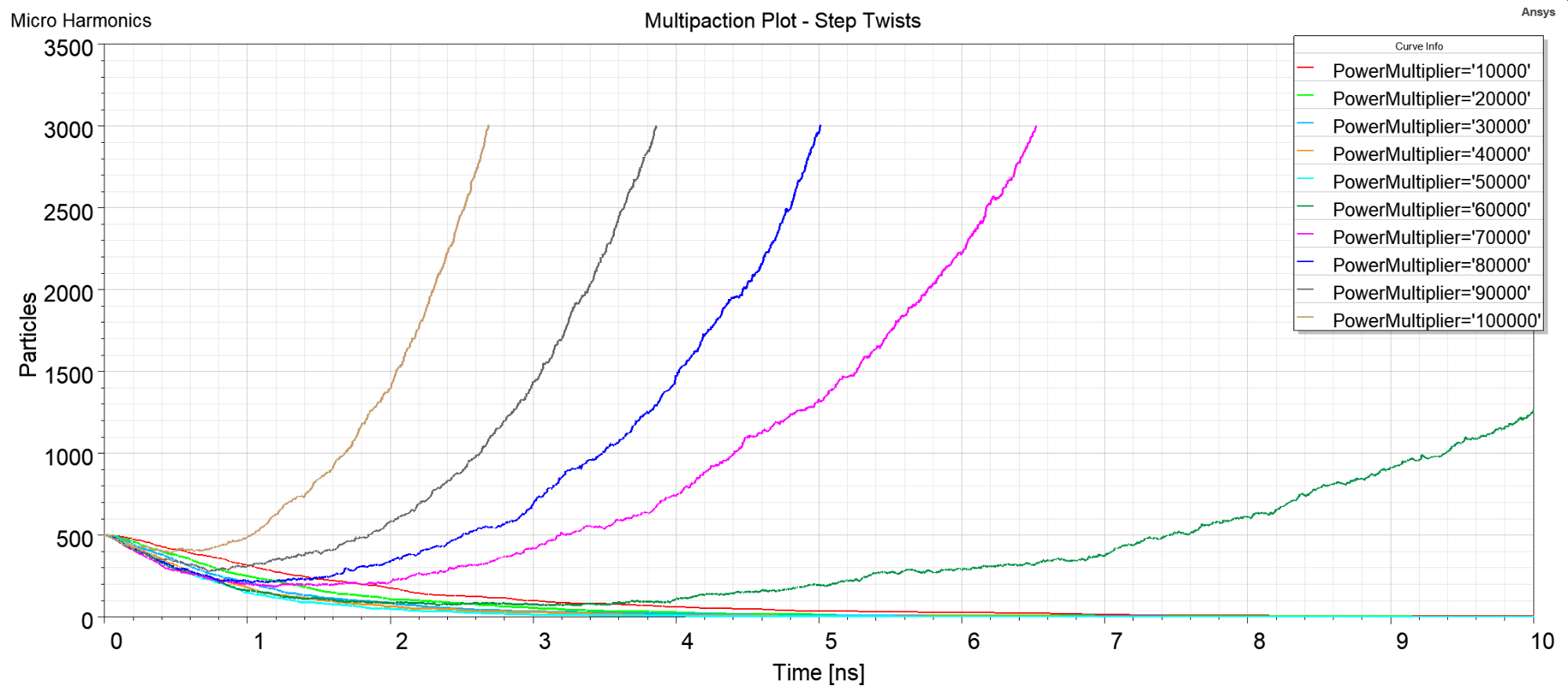
Figure 6 – Multipaction simulation results for the WR-5.1 45° twist step model.
Faraday Rotator
Secondary electron emission (SEE) boundaries were defined on all metal surfaces of the Faraday rotator. The Faraday rotator model is more complicated than the OMT and twist step models due to the presence of the dielectric materials (ferrite rod, alumina cones, and magnetic absorber). The dielectric materials are capable of generating secondary electrons, but our initial models did not include any provision for this. The electromagnetic fields permeate the entire volume of the dielectric materials. The field intensity is low in the absorber, but high in the ferrite rod where the vast majority of the RF signal power is contained within the primary HE11 propagating mode.
Charged particles were also seeded within the absorber, ferrite, and alumina materials. Signals travelling through the ferrite rod are contained within the HE11 mode. The vast majority of the RF signal power in the HE11 mode is contained within the ferrite rod with only small fringing fields existing outside the rod. Higher order modes outside the ferrite rod are suppressed by the absorber material. Charged particles outside the ferrite rod are accelerated by the weaker fringing fields.
Multipaction analysis results from our models of the Faraday rotator are shown in Figure 7. A single excitation was used on the single-mode port. There were no excitations on the OMT common mode port. The simulations indicate that multipaction does not occur at RF powers below 100 kW. Multipaction is however indicated at power levels above 150 kW. The high power levels needed for multipaction may simply be due to the low intensities of the fringing fields outside the ferrite rod.
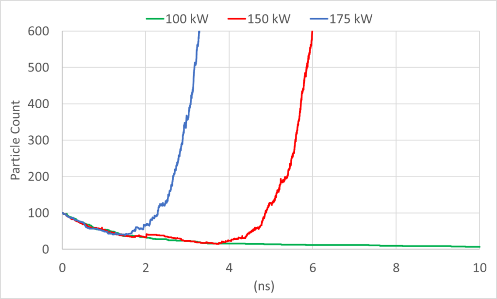
Figure 7 – Multipaction analysis for the WR-5.1 Faraday rotator. A single excitation at 180 GHz was used on the single mode port. The model was seeded with 100 charged particles.
The models were refined with SEE boundaries defined on the outer surface of the ferrite rod (Figure 8a) and the inner surface of the absorber (Figure 8b). A multipaction charge region was defined within the volume bounded by the two SEE boundaries as indicated in Figure 8c.
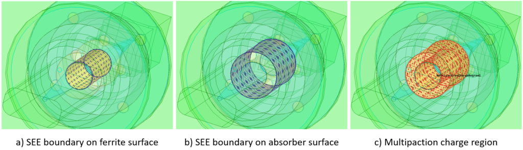
Figure 8 – SEE boundaries and multipaction charge region.
The results of the multipaction analysis are shown in Figure 9. Multipaction is not evident at RF power levels below 0.5 MW. Multipaction is evident at RF excitations above 1 MW.
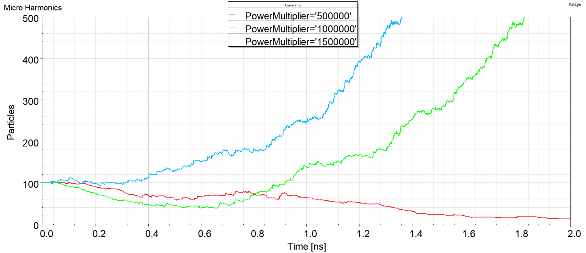
Figure 9 – Multipaction results with SEE boundaries on the outer ferrite and inner absorber surfaces. One hundred charged particles were seeded in the region between the two SEE boundaries.
Figure 10 shows a plot of the electric field in our model. The EM fields are strong inside the waveguides and the ferrite rod, but weak in the area surrounding the ferrite rod where the charged particles are located. This is why such high RF power levels are required to cause multipaction in this region. The plot in Figure 10 also shows residual charged particles within the charged particle region where the EM field intensity is very low. Particles that appear to be inside the ferrite rod are actually above the rod and located within the charge region.
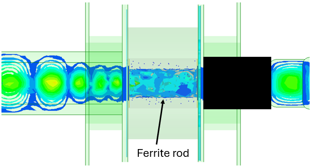
Figure 10 – Multipaction results with SEE boundaries on the outer ferrite and inner absorber surfaces. One hundred charged particles were seeded in the region between the two SEE boundaries.
There was some uncertainty in the SEE boundary definitions for the absorber and ferrite materials. In our simulations we used the same SEE definitions used for metal surfaces. But it is highly unlikely that multipaction is an issue in the Faraday rotator or in the larger hybrid circulator due to the fact that maximum RF excitations in WR-5.1 are not likely to exceed 2 W.
Multipaction Analysis Summary
Multipaction analysis was run on all sections of the hybrid circulator using the tool in Ansys HFSS. The lowest threshold for multipaction was found to be for an RF signal near 50 kW in the OMT section. This threshold was reached when both polarizations were simultaneously excited. The rated RF power for the hybrid circulator varies by band but is generally less than 3W. The multipaction threshold is thus more than three orders of magnitude higher than the maximum power rating for the hybrid circulator.
Micro Harmonics specializes in the design and manufacture of high-performance microwave components and systems for scientific and industrial applications. If you have any questions about this or any of our products, such as circulators, isolators, or attenuators, please feel free to contact us!
References
[1] J. R. M. Vaughan, “Multipactor,” in IEEE Trans. on Elec. Dev., vol. 35, no. 7, pp. 1172-1180, July 1988.
[2] H. Ren and Y. Xie, “Simulations of the Multipactor Effect in Ferrite Circulator Junction with Wedge-Shaped Cross Section Geometry,” in IEEE Transactions on Electron Devices, vol. 67, no. 11, pp. 5144-5150, Nov. 2020
[3] D. W. Porterfield, “Broadband Millimeter-Wave Hybrid Circulators,” IEEE Trans. Microw. Theory Techn., vol. 71, no. 8, pp. 3501-3507, Aug. 2023.
[4] C. E. Barnes, “Broad-band isolators and variable attenuators for millimeter wavelengths,” IRE Trans. Microw. Theory Tech., vol. 9, no. 6, pp. 519-523, Nov. 1961.
[5] N. R. Erickson, “Very low loss wideband isolators for mm-wavelengths,” in IEEE MTT-S Int. Microw. Symp. Dig., Phoenix, Az., vol. 2, 2001, pp. 1175-1178.
[6] High Frequency Structure Simulator (HFSS), Ansys Corporation.
[7] A. Dunning, S. Srikanth, and A. R. Kerr, “A simple orthomode transducer for centimeter to submillimeter wavelengths,” in Proc. Int. Symp. Space Terahertz Technol., Charlottesville, VA, Apr. 2009, pp. 191–194.
[8] T. J. Reck and G. Chattopadhyay, “A 600 GHz asymmetrical orthogonal mode transducer,” IEEE Microw. Wireless Compon. Lett., vol. 23, no. 11, pp 569-571, Nov. 2013.