
Orthomode Transducers: Part 5 – RF Testing with a Matched Load
David W. Porterfield, PhD
Founder, Micro Harmonics
This is the fifth blog in a series on orthomode transducers [1–4]. In earlier posts, we introduced orthomode transducers (OMTs) and their applications [1], explored several common OMT architectures [2], and outlined the key performance parameters used to evaluate them [3]. In the previous blog [4], we demonstrated how to obtain useful RF test data using a simple short circuit termination on the common mode port. In this fifth blog, we will describe RF testing methods using a matched load on the common mode port.
OMT Description
OMTs have three waveguide ports. Two of the ports support a single TE10 propagating mode in a rectangular waveguide. The third port, the common mode port, supports two orthogonal propagating modes. The common-mode waveguide can have a square cross-section, supporting orthogonal TE10 and TE01 modes, or a circular cross-section, supporting a pair of degenerate orthogonal TE11 modes.
Figure 1 shows a simplified sketch of an OMT. Port 1 on the axial waveguide and port 2 on the lateral waveguide each support a single TE10 mode. The common-mode waveguide supports two polarizations designated as vertical (V) and horizontal (H). The two modes can be treated as two distinct ports, port 3 (V) and port 4 (H). The vertical (V) and horizontal (H) designations simply help us keep track of the associated polarizations. An ideal OMT couples 100% of the vertically polarized signal between ports 1 (V) and port 3 (V) and 100% of the horizontally polarized signal between ports 2 (H) and port 4 (H).
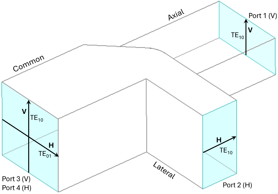
Figure 1 – Simplified asymmetric T-Junction OMT with polarization and port designations.
Difficulties of Characterizing OMTs
RF testing of OMTs is complicated by the presence of the common mode port, which supports two orthogonal modes. Vector network analyzers have single-mode test ports. The question is how to handle the common-mode port in testing.
Testing with a Matched Load on the Common Mode Port
The short circuit test described in the previous blog [4] provides useful data for insertion loss and qualitative data for isolation and cross-polarization coupling. But the short circuit test does not yield any information on the characteristic OMT port reflections (S11, S22, S33, S44). In the short circuit tests, the large port reflections seen at ports 1 and 2 are interpreted as transmission data, but they could mask large OMT port reflections. One way to obtain more accurate reflection data is to replace the short circuit termination on the common mode port with a matched load.
Dual-polarized matched loads are not readily available on the commercial market but can be designed and fabricated at considerable cost. They can take the form of a simple square waveguide with a lossy dielectric cone at one end, with the cone tip centered in the waveguide, as shown in Figure 2. The architecture is similar to the metrological grade-matched loads commonly found in rectangular waveguide calibration kits.
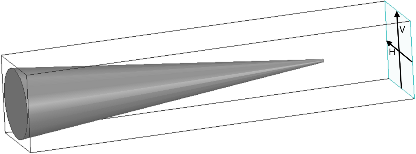
Figure 2 – Dual polarization matched load comprising a lossy dielectric cone in a square waveguide.
If a dual-polarized matched load is attached to the OMT common-mode port, the S11 and S22 port reflections can be measured directly by connecting a vector network analyzer to ports 1 and 2 of the OMT. The OMT is reciprocal, so the magnitudes of the port reflections on the common mode port (S33 and S44) are also known since |S33| = |S11| and |S44| = |S22|. Both the S21 and S12 isolation parameters can also be measured.
Precision machining of the lossy dielectric cone is challenging at the higher mm-wave frequencies. Precision alignment of the cone in the waveguide is also difficult. An alternative is to fabricate a simple waveguide taper having a square waveguide port on one end and a rectangular waveguide port at the other end, as shown in Figure 3. The square waveguide supports both the TE10 and TE01 modes. The TE10 mode on the square waveguide port is coupled via the taper to the TE10 mode on the rectangular waveguide port. The TE01 mode is cut off as the taper narrows and is thus open-circuited. (A resistive fin can be added to absorb the TE01 signal, but that significantly complicates the fabrication.)
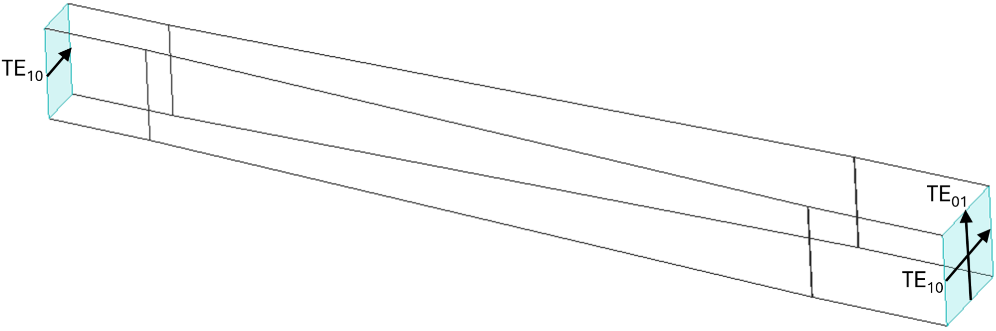
Figure 3 – Linear taper from square waveguide to rectangular waveguide. The TE10 mode in the square waveguide is coupled to the TE10 mode in the rectangular waveguide via the taper. The TE01 mode in the square waveguide is cut off as the taper narrows.
If the taper is attached to the OMT at the common port and a rectangular waveguide matched load is attached to the rectangular waveguide port on the other end of the taper, a matched load is provided for one of the two polarizations on the common mode port of the OMT. If the taper and load are removed from the OMT, rotated 90°, and then reattached, the opposite polarization now sees a matched load. This allows measurement of both the S11 and S22 port reflections (see Figure 1). This method does reintroduce one of the cross-polarization terms in the isolation measurement, but the effect should be small.
The waveguide tapers can be calibrated by attaching two of them together at the common mode ports (the square waveguides). The tapers can also be used to calibrate a dual-mode matched load.
Advancing OMT Testing with Practical Solutions
Testing orthomode transducers with a matched load offers a more complete and dependable way to evaluate key performance metrics, especially when accurate reflection data is required. While short-circuit methods remain useful for quick insights, matched-load techniques reduce uncertainty and provide a clearer picture of the device’s true behavior. Approaches such as dual-polarized loads or waveguide taper configurations make it possible to overcome common testing challenges without overly complex setups.
At Micro Harmonics, we support these efforts with precision-engineered solutions, including orthomode transducers, attenuators, isolators, and circulators, helping engineers achieve consistent, high-quality measurement results. If you have any questions, don’t hesitate to reach out to our team.
References
[1] D. Porterfield, “Orthomode Transducers: Part 1 – Introduction and Applications,” A brief description of orthomode transducers (OMTs) and common applications. https://microharmonics.com/blog/, January 31, 2025.
[2] D. Porterfield, “Orthomode Transducers: Part 2 – Architectures,” A brief description of some of the most common mm-wave OMT architectures. https://microharmonics.com/blog/, May 21, 2025
[3] D. Porterfield, “Orthomode Transducers: Part 3 – Characterization,” A description of important OMT parameters including insertion loss, port reflections, cross-polarization coupling, and isolation. https://microharmonics.com/blog/, 2026
[4] D. Porterfield, “Orthomode Transducers: Part 4 – RF Testing with a Short Circuit Termination,” How to measure insertion loss and qualitatively characterize isolation and cross-polarization coupling using a short circuit termination on the common mode port. https://microharmonics.com/blog/, 2026