
Orthomode Transducers: Part 2 – Architectures
David W. Porterfield, PhD
Founder, Micro Harmonics
In our previous blog, “Orthomode Transducers: Part 1 – Introduction and Applications“, we provided an preliminary examination of orthomode transducers (OMTs) and their applications. In this post, we will explore the OMT architecture.
OMTs have three waveguide ports. Two ports support a single propagating mode, typically the TE10 mode in a rectangular waveguide. The third port, often referred to as the common mode port, supports two orthogonal propagating modes. The common mode waveguide can have a square cross-section supporting the orthogonal TE10 and TE01 modes or a circular cross-section supporting a pair of degenerate orthogonal TE11 modes.
Symmetric vs Asymmetric
OMTs come in a broad range of topologies, which generally fall into two categories, symmetric and asymmetric.
- Asymmetric OMTs are simpler and easier to fabricate. Their fractional bandwidth is typically limited to less than 30% because the asymmetry excites higher-order modes in the common waveguide.
- Symmetric OMTs can be designed to cover entire rectangular waveguide bands (40%). Although higher-order modes can propagate in the common mode waveguide, symmetry in the structure ensures that they are not excited.
Example: W-Band OMT with a Square Common Mode Waveguide
Consider an OMT operating in a W-band with a square common-mode waveguide. The recommended WR-10 operating bandwidth is 75-110 GHz.
- The rectangular waveguides on the two single-mode OMT ports have a cross-section of (0.1 x 0.05 inch) [2.54 x 1.27 mm]. The rectangular waveguides support a single TE10 mode in the standard WR-10 band, which covers 75-110 GHz. The TE10 mode cutoff frequency is 59 GHz.
- The square common mode waveguide has dimensions (0.1 x 0.1 inch) [2.54 x 2.54 mm]. The TE10 and TE01 modes propagate over the 75-110 GHz band, both having cutoff frequencies of 59 GHz.
- Two higher-order modes, the TE11 and TM11, have a cutoff frequency of 83.5 GHz, which is within the standard 75-110 GHz band. Asymmetry in the OMT structure can easily excite these modes, but symmetric structures do not.
- The next set of higher-order modes are the TE02 and TE20, which have cutoff frequencies of 118 GHz, outside the standard WR-10 band.
Rectangular vs. Circular Waveguides
It should be noted that a rectangular waveguide has a broader bandwidth than a circular waveguide. The second propagating mode in the rectangular waveguide, the TE20 mode, has a cutoff frequency twice that of the primary TE10 mode. In our WR-10 example, the TE10 has a cutoff frequency of 59 GHz, and the TE20 mode has a cutoff frequency of 118 GHz.
The fractional bandwidth where only the TE10 mode propagates is about 67% (Bandwidth / Center Frequency = 59 GHz / 88.5 GHz ~ 67%). Fractional bandwidths are closer to 40% for standard rectangular waveguides due to safety margins at the high end of the band and rapidly changing waveguide impedances at the low end of the band.
The second propagating mode in a circular waveguide, the TM01 mode, has a cutoff frequency only 1.3 times the cutoff frequency of the primary TE11 mode. The fractional bandwidth where only the TE11 mode propagates is about 27%, less than half the bandwidth of the rectangular waveguide.
Additional OMT Design Structures
There are a variety of asymmetric OMT structures found in the literature. An asymmetric T-Junction OMT [1,2] is shown in Figure 1. Although the structure is somewhat complicated, it is not too difficult to envision how the vertical mode (V) in the common section is coupled to the axial arm, while the horizontal mode (H) is coupled to the lateral arm.
This OMT is easy to machine in a split waveguide block. There is an H-plane split in the axial waveguide which requires precision machining and additional clamping screws. A step-twist can be added to rotate the axial waveguide into the E-plane split.
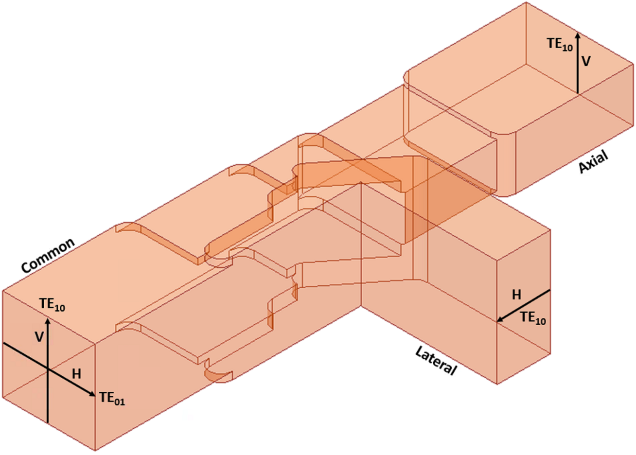
Figure 1 – Asymmetric T-Junction OMT.
A symmetric Bøifot OMT [3, 4] is shown in Figure 2. The metal septum directs the vertical and horizontal polarizations along separate paths. The septum couples the horizontal mode (H) to the two lateral arms. The horizontally polarized signals are then recombined and coupled to a single-mode TE10 rectangular port.
The vertical mode propagates past the septum to the axial waveguide section, transitions to the vertical waveguide, and is coupled to a single-mode TE10 rectangular port. Although the higher-order TE11 and TM11 modes can propagate in the square common-mode waveguide, they are not excited in the symmetric Bøifot structure. Bøifot OMTs have been reported with fractional bandwidths exceeding 40%.
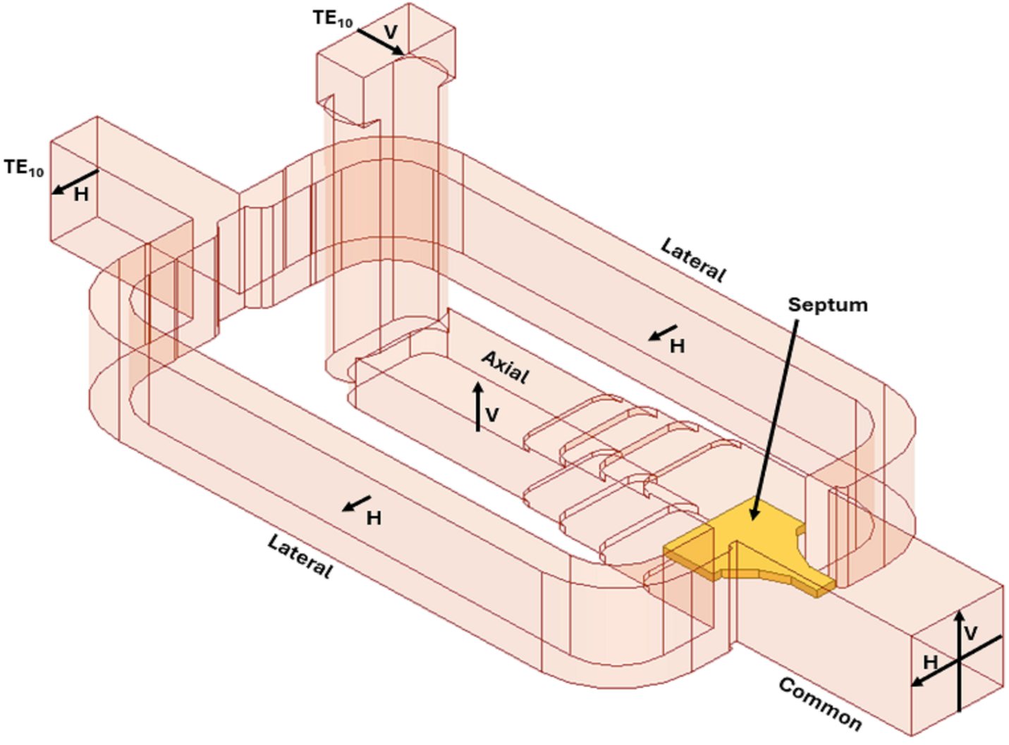
Figure 2 – Symmetric Boifot OMT.
Another common symmetric OMT structure is the turnstile [5, 6]. The turnstile OMT uses a circular common-mode waveguide. The turnstile junction is the convergence of a circular waveguide and four rectangular waveguides, as shown in Figure 3. One nice feature of the turnstile OMT is the ease of mating a conical horn to the circular waveguide. The symmetry of the turnstile junction yields very broad bandwidth operation. However, it is difficult to fabricate the turnstile OMT due to the complexity of recombining two sets of waveguides.
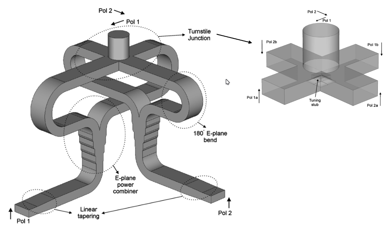
Figure 3 – Sketch of a turnstile OMT, from Fig. 1 & Fig. 3, Navarrini & Plambeck [5].
Looking Ahead
There are many other symmetric OMT structures described in the literature, including the reverse-coupling waveguide [7]. Each has unique advantages and disadvantages in terms of RF performance and ease of fabrication. In our next blog in this series, we will look at the difficulties of accurately characterizing OMT structures.
At Micro Harmonics, we specialize in developing high-quality attenuators, circulators, isolators, as well as innovative orthomode transducers, designed to meet the demanding requirements of modern communication systems. Stay tuned for the next installment in this blog series, where we will delve deeper into the challenges of characterizing these cutting-edge OMT structures and how our products are engineered to overcome them.
References
[1] A. Dunning, S. Srikanth, and A. R. Kerr, “A simple orthomode transducer for centimeter to submillimeter wavelengths,” in Proc. Int. Symp. Space Terahertz Technol., Charlottesville, VA, Apr. 2009, pp. 191–194.
[2] T. J. Reck and G. Chattopadhyay, “A 600 GHz asymmetrical orthogonal mode transducer,” IEEE Microw. Wireless Compon. Lett., vol. 23, no. 11, pp 569-571, Nov. 2013.
[3] A. M. Bøifot, E. Lier, and T. Schaug-Pettersen, “Simple and broadband orthomode transducer (antenna feed),” in Proc. IEE H-Microw. Antennas and Propag., vol. 137, no. 6, pp. 396–400, Dec. 1990.
[4] E. J. Wollack, W. Grammer, and J. Kingsley, “The Boifot orthomode junction,” Nat. Radio Astron. Observatory, Tucson, AZ, USA, ALMA Memo 425, May 2002.
[5] A. Navarrini and R. L. Plambeck, “A turnstile junction waveguide orthomode transducer,” in IEEE Trans. Microw. Theory Tech., vol. 54, no. 1, pp. 272-277, Jan. 2006.
[6] G. Pisano et al., “A broadband WR10 turnstile junction orthomode transducer,” IEEE Microw. Wireless Compon. Lett., vol. 17, no. 4, pp. 286–288, Apr. 2007.
[7] A. Navarrini and R. Nesti, “Symmetric reverse-coupling waveguide orthomode transducer for the 3-mm band,” IEEE Trans. Microw. Theory Techn., vol. 57, no. 1, pp. 80–88, Jan. 2009.