
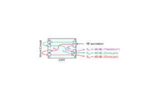
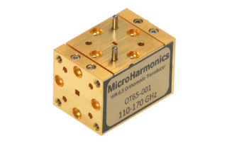
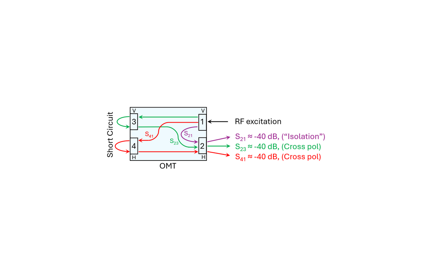
Orthomode Transducers: Part 4 – RF Testing with a Short Circuit Termination
Orthomode Transducers: Part 4 – RF Testing with a Short Circuit Termination David W. Porterfield, PhD Founder, Micro Harmonics In previous blogs, we gave a brief introduction to orthomode transducers (OMTs) and their applications [1], showed some of the common OMT architectures [2], and described the important parameters of OMTs, including insertion loss, port reflections, cross-polarization coupling, and isolation [3]. In this fourth post, we [...]
Orthomode Transducers: Part 3 – Characterization
Orthomode Transducers: Part 3 – Characterization David W. Porterfield, PhD Founder, Micro Harmonics In previous blogs, "Orthomode Transducers: Part 1 – Introduction and Applications" and "Orthomode Transducers: Part 2 – Architectures", we gave a brief description of orthomode transducers (OMTs), discussed some applications, and described some basic architectures. In this third post, we will examine the important characteristics of OMTs and explain why it is [...]
When MMW Challenges Push the Limits of Design, We Reengineer What’s Possible
When MMW Challenges Push the Limits of Design, We Reengineer What’s Possible Micro Harmonics was founded on the clear belief that advancement at millimeter wave (MMW) and terahertz (THz) frequencies requires components designed to resolve industry challenges. We are committed to listening to our customers, learning about their needs, and designing innovative solutions. The pace of innovation in radio astronomy, quantum computing, and high-frequency test [...]
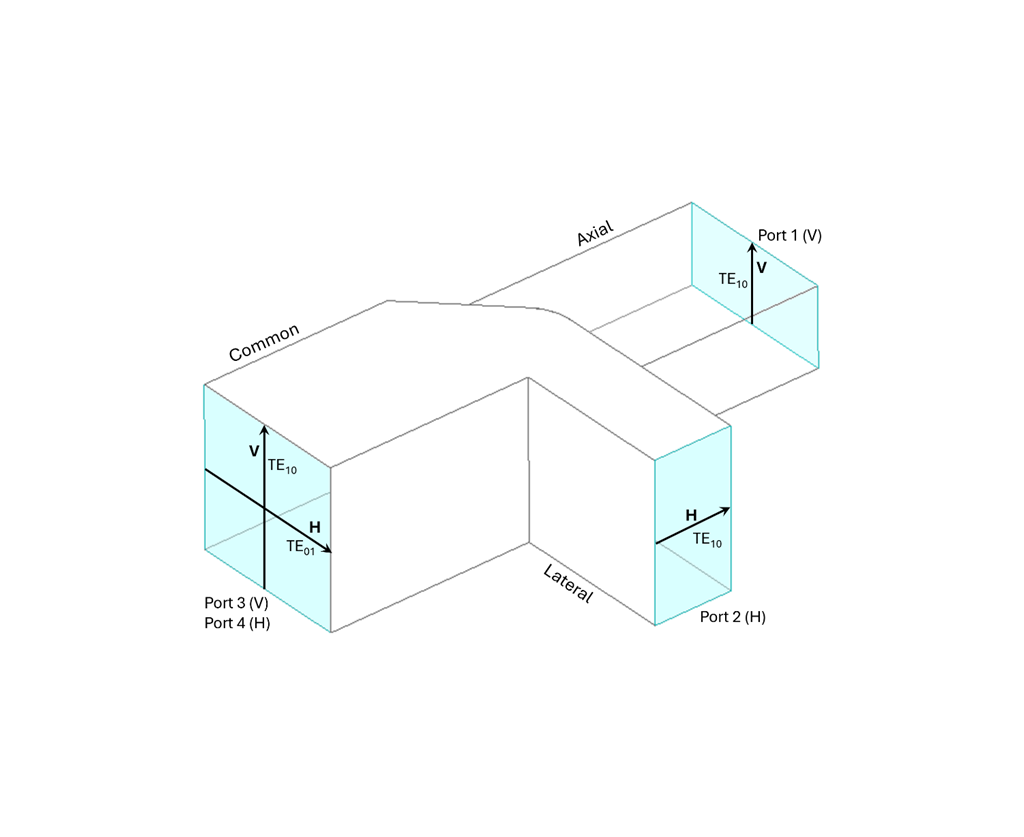
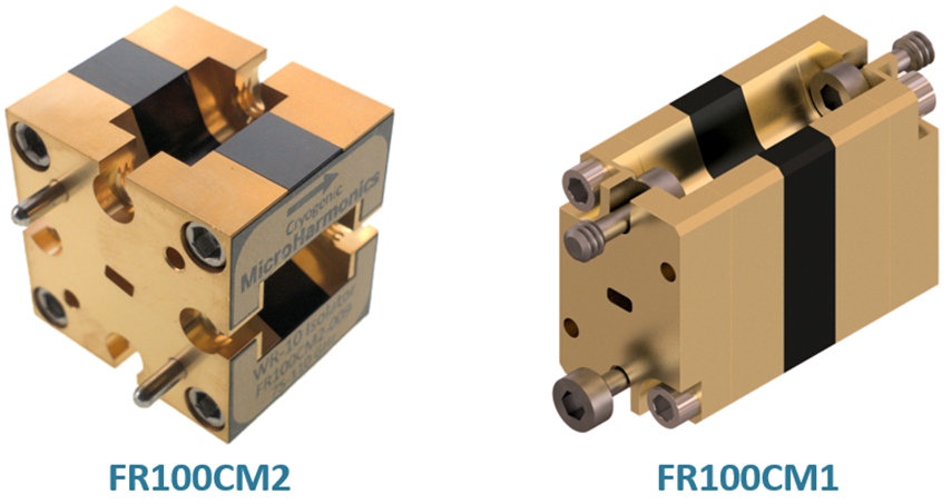
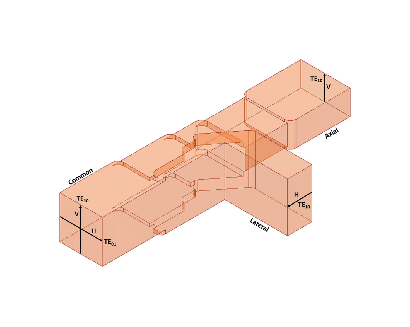
Orthomode Transducers: Part 2 – Architectures
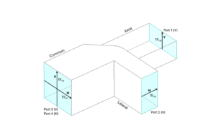
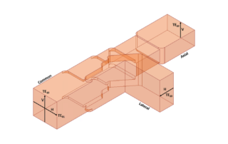
Orthomode Transducers: Part 2 – Architectures David W. Porterfield, PhD Founder, Micro Harmonics In our previous blog, "Orthomode Transducers: Part 1 – Introduction and Applications", we provided an preliminary examination of orthomode transducers (OMTs) and their applications. In this post, we will explore the OMT architecture. OMTs have three waveguide ports. Two ports support a single propagating mode, typically the TE10 mode in a rectangular [...]
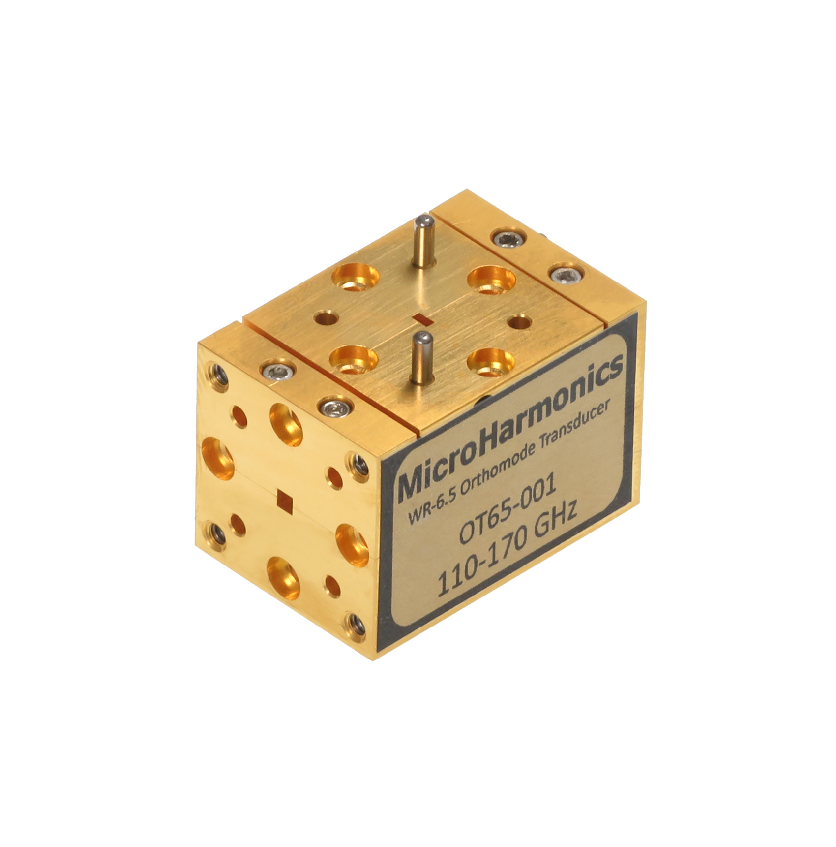
Orthomode Transducers: Part 1 – Introduction and Applications
Orthomode Transducers: Part 1 – Introduction and Applications David W. Porterfield, PhD Founder, Micro Harmonics Orthomode transducers (OMTs), also known as polarization duplexers, are waveguide components that combine or separate two orthogonally polarized signals. OMTs have three waveguide ports. Two of the ports support a single propagating mode, typically the TE10 mode in rectangular waveguide. The third port, often referred to as the common mode [...]
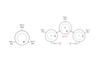
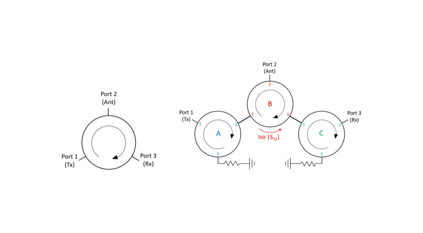
A mm-Wave Circulator with High Transmitter and Receiver Isolation (Part 2)
A mm-Wave Circulator with High Transmitter and Receiver Isolation (Part 2) David W. Porterfield, Ph.D. President and Founder Micro Harmonics Corporation In last month’s blog, I showed why a triple junction circulator offers no advantage over a single junction circulator in isolating a sensitive receiver from a high-power transmitter (S31). I also showed that the new Micro Harmonics hybrid circulators [1] can achieve much higher [...]