
Orthomode Transducers: Part 1 – Introduction and Applications
David W. Porterfield, PhD
Founder, Micro Harmonics
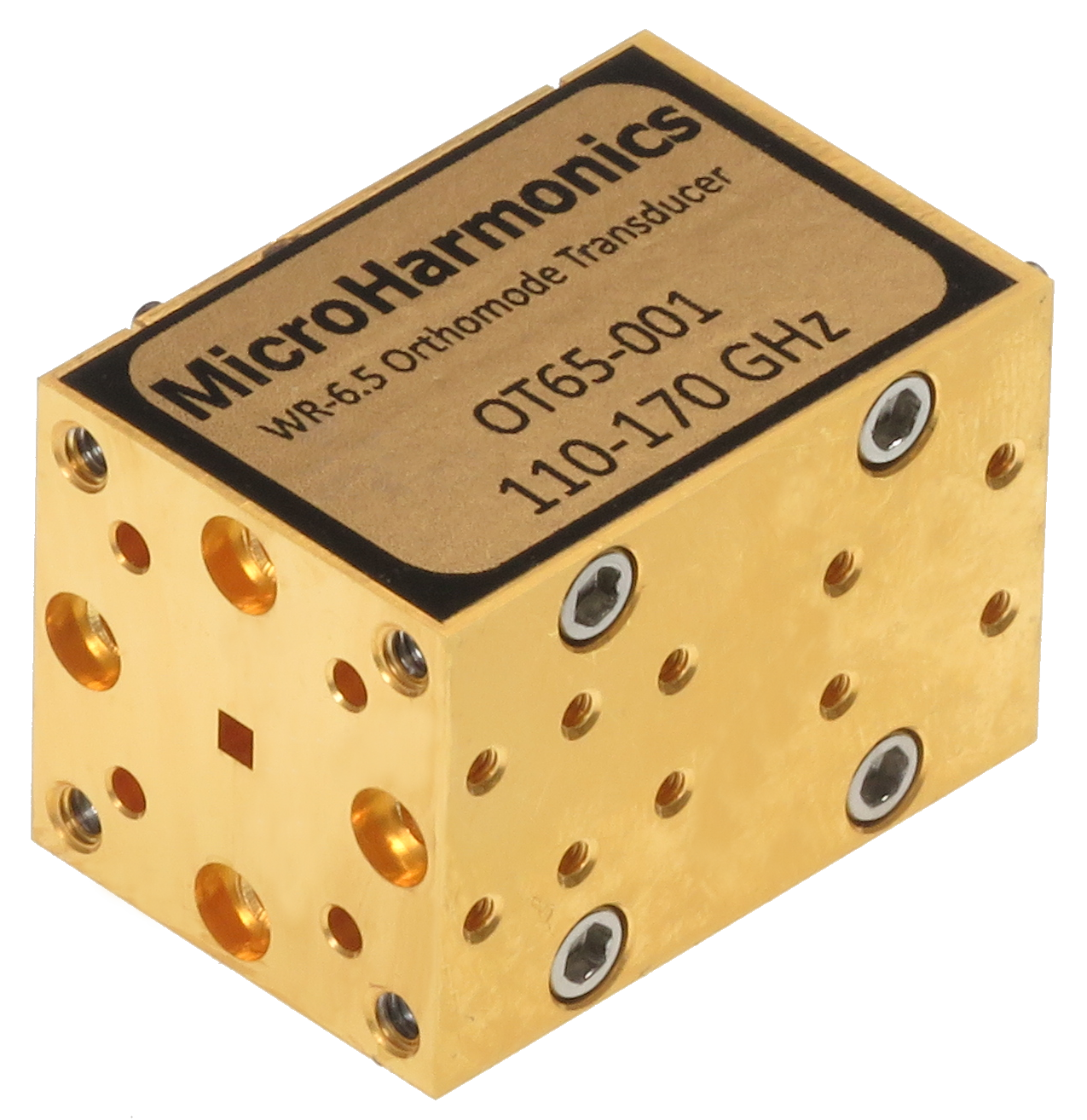
Orthomode transducers (OMTs), also known as polarization duplexers, are waveguide components that combine or separate two orthogonally polarized signals. OMTs have three waveguide ports. Two of the ports support a single propagating mode, typically the TE10 mode in rectangular waveguide. The third port, often referred to as the common mode port, supports two orthogonal propagating modes. The common mode waveguide can have a square cross-section supporting the orthogonal TE10 and TE01 modes, or a circular cross-section supporting a pair of degenerate orthogonal TE11 modes.
In the second part of this series, we will discuss OMT architecture and modes in more detail.
VSAT Systems: Enabling High Isolation Between Signals
OMTs are commonly used in microwave and mm-wave telecommunications systems.
One example is Very Small Aperture Terminal (VSAT) systems. In VSAT, the transmission and reception paths are at 90° with respect to each other. This orthogonal orientation provides very high isolation between the two signals.
The OMT protects the receiver or low noise block downconverter (LNB) from the high output power of the block upconverter (BUC). Wikipedia has some good articles with additional information on OMTs [1] and how they are used in VSAT systems [2].
Terrestrial Microwave Links: Enhancing Data Throughput
OMTs are also found in terrestrial microwave radio links. A pair of parabolic reflectors operate in a point-to-point microwave radio path using four radios (two at each end). Here, OMTs are mounted at the parabolic feed, separating the signal from the feed into two separate radios, one operating in the horizontal polarity and the other in the vertical polarity. This arrangement is used to increase the aggregate data throughput between two dishes on a point-to-point microwave path or for fault-tolerance redundancy.
Certain types of outdoor microwave radios have integrated orthomode transducers and operate in both polarities from a single radio unit, performing cross-polarization interference cancellation within the radio unit itself. Alternatively, the orthomode transducer may be built into the antenna, allowing for the connection of separate radios or separate ports of the same radio to the antenna.
OMTs in Radio Astronomy: Unlocking the Secrets of the Universe
OMTs are also commonly used in radio astronomy to detect and analyze polarized radio waves from celestial sources [3]. The OMT separates orthogonal polarization modes of incoming electromagnetic waves, enabling astronomers to study the polarization properties of radio signals with high precision.
Measuring Stokes Parameters for Polarization Analysis
By separating the orthogonal polarization components, OMTs allow astronomers to measure the Stokes parameters, which describe the polarization state of the electromagnetic waves [5]. This information is vital for understanding the magnetic fields in various astronomical objects and the interstellar medium.
Studying Cosmic Microwave Background Radiation
OMTs are used in experiments studying Cosmic Microwave Background (CMB) radiation. The polarization of the CMB can provide insights into the early universe, including information about inflation and the large-scale structure of the cosmos. High-precision OMTs are essential for minimizing cross-polarization and ensuring accurate measurements [3].
Mapping Galactic Emissions with OMTs
Another example is the Galactic Emission Mapping (GEM) project where OMTs are used to map the polarized emission from our galaxy. These maps are essential for distinguishing between different sources of radio emission, such as synchrotron radiation and thermal emission, and are crucial for decontaminating CMB data.
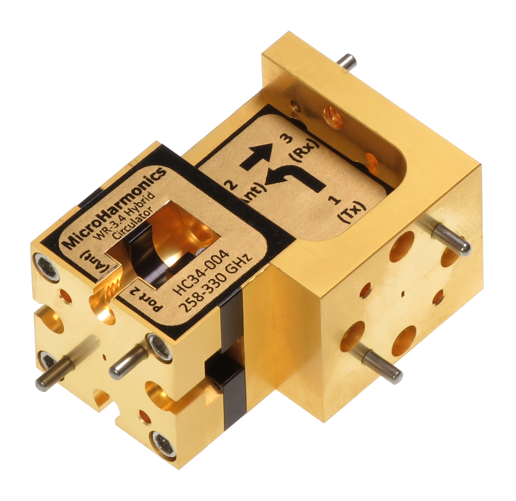
Innovations in OMT Technology: The Hybrid Circulator
Micro Harmonics has been developing orthomode transducers (OMTs) for several years. Our OMT is an integral part of our patented hybrid circulator technology [4, 5], which has made broadband circulators a reality in the mm-wave bands. In the hybrid circulator, the OMT is coupled to a Faraday rotator to achieve the circulator function. When used in a transmit/receive system, the hybrid circulator isolates the transmitter from the receiver like the OMT systems described earlier. However, unlike the OMT systems, the hybrid circulator allows both transmit and receive signals to share the same polarization.
Hybrid circulators are now available in every standard waveguide band from WR-15 to WR-3.4 (50 GHz to 330 GHz) with fractional bandwidths of 24%. We have now demonstrated that our hybrid circulator can be configured to cover full waveguide bands (40%) with more than 20 dB isolation between the ports. A D-band version (model HC065F) is now available, covering the full band from 110-170 GHz [6].
Additional full-band hybrid circulators up to the WR-3.4 band (220-330 GHz) are under development. In our upcoming blogs in this series, we will look at OMT architectures and the challenges of OMT characterization.
References
[1] Wikipedia article on OMTs, https://en.wikipedia.org/wiki/Orthomode_transducer
[2] Wikipedia article on VSAT systems, https://en.wikipedia.org/wiki/Very-small-aperture_terminal
[3] Ferreira, I.S., Tello, C., Bergano, M. et al. A C-band broadband ortho-mode transducer for radioastronomy polarimetry. SpringerPlus 5, 2069 (2016). https://doi.org/10.1186/s40064-016-3761-5
[4] D. W. Porterfield, “Broadband Millimeter-Wave Hybrid Circulators,” IEEE Trans. Microw. Theory Techn., vol. 71, no. 8, pp. 3501-3507, Aug. 2023.
[5] The hybrid circulator is protected under US patent 12034196 and EPO patent 4121815.
[6] Micro Harmonics D-band hybrid circulator, https://microharmonics.com/millimeter-wave-circulators/