| Model | Flange (EIA) | Band (GHz) | Dynamic Range (dB, Min) | Insertion Loss (dB, Avg) | Max Power (dBm | W) | Status |
|---|---|---|---|---|---|---|
| VA148 | WR-15 | 50–75 | Under development | |||
| VA122 | WR-12 | 60–90 | Under development | |||
| VA100 | WR-10 | 75–110 | 0–35 | 1.2 | 34 | 2.3 | Now available |
| VA080 | WR-8 | 90–140 | 0–30 | 0.8 | 34 | 2.4 | Now available |
| VA065 | WR-6.5 | 110–170 | 0–35 | 1.5 | 32 | 1.5 | Now available |
| VA051 | WR-5.1 | 140–220 | Under development | |||
| VA043 | WR-4.3 | 170–260 | Under development | |||
| VA034 | WR-3.4 | 220–325 | Under development |
Distinctives
- Lowest insertion loss
- Electrically controllable
- No moving parts
- Not ESD sensitive
- Full band
- Smallest form factor
- Full band test data
- Direct engineering support
Applications
- Equalization
- Calibration
- Switching
- Power control
- Power sweeps
- Power characterization
- Test equipment
- Instrumentation
- Test setups
Our attenuators use Faraday rotation in a ferrite rod to rotate an RF signal into a fixed resistive vane. The attenuation level is set using a simple DC voltage in the range from 0–10 V. They are configured so that maximum attenuation is achieved at 0 V bias
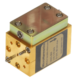
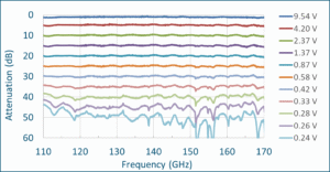
The attenuator is compact, lightweight, and has no moving parts. The small size makes the attenuator very easy to fit into millimeter-wave systems. The technology is passive and insensitive to ESD damage. Our attenuators can handle significantly higher power levels than PIN attenuators. Measured data from our D-band WR-6.5 attenuator is shown below. The dynamic range is more than 35 dB. The WR-6.5 attenuator has a power rating of 1.5 W.
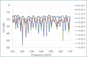
An important advantage of the ferrite attenuator is the relatively low port reflections. The graph below shows measured reflections on Port 1 at the various attenuation levels of the WR-6.5 attenuator. The reflections are less than -14 dB across the band for every attenuation level. This compares favorably to the port reflections found on PIN attenuators which can approach -5 dB.
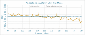
Our variable attenuators have short rise and fall times, have no moving parts, and are electrically controlled. This enables reliable and repeatable point-by-point tuning and control at 1-5 ms per point. For high dynamic range and high flatness applications, the variable attenuator can be flattened out with point-by-point voltage control. Below is an example of an F-band variable attenuator at about 25 dB attenuation. The gold line represents attenuation with a DC bias, and the blue line represents flattened attenuation with point-by-point tuning.
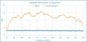
Point-by-point tuning also enables equalization of an external source. This concept is demonstrated below by equalizing a signal varying 10 dB across the WR-8 band (represented by the gold line). The variable attenuator has been used as an equalizer to flatten this signal (represented by the blue line).