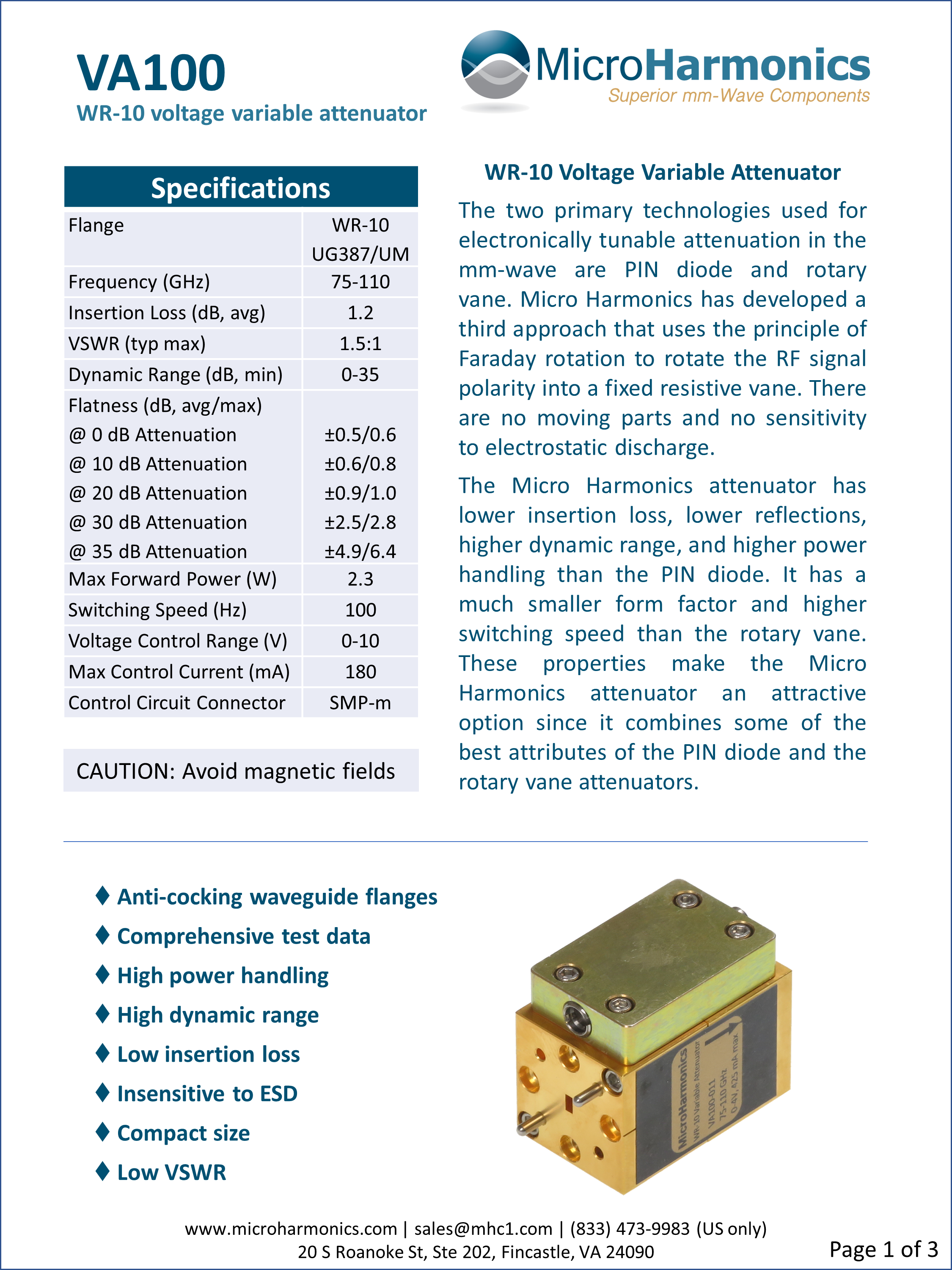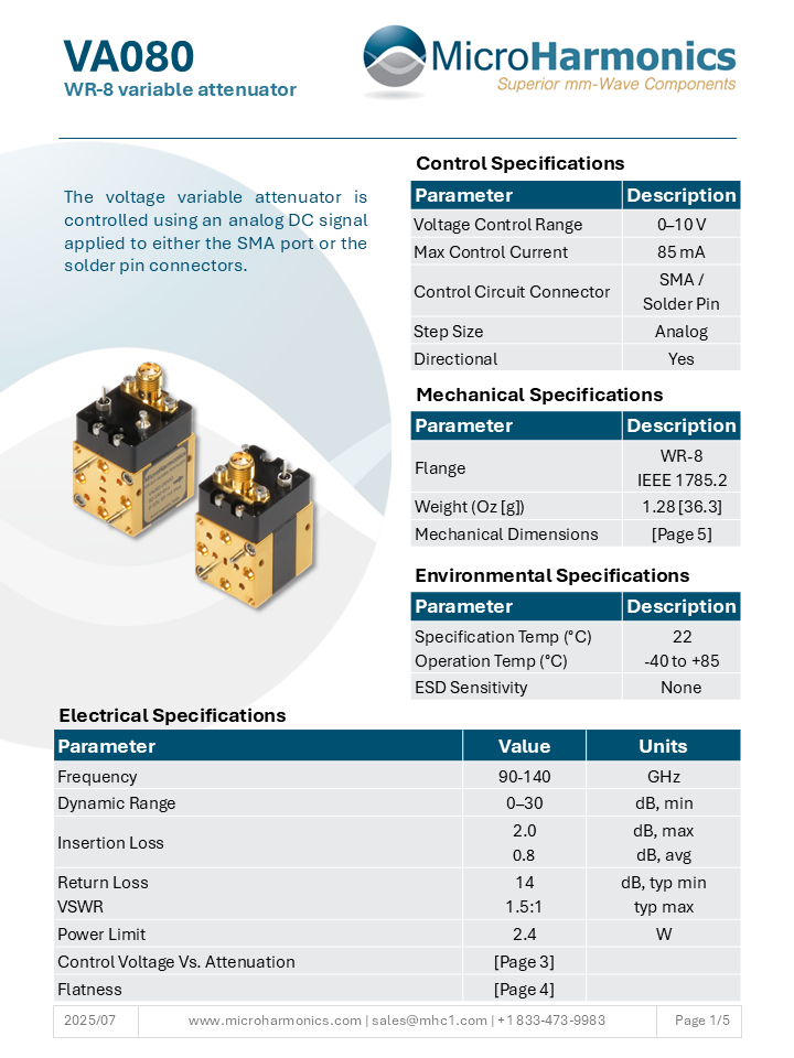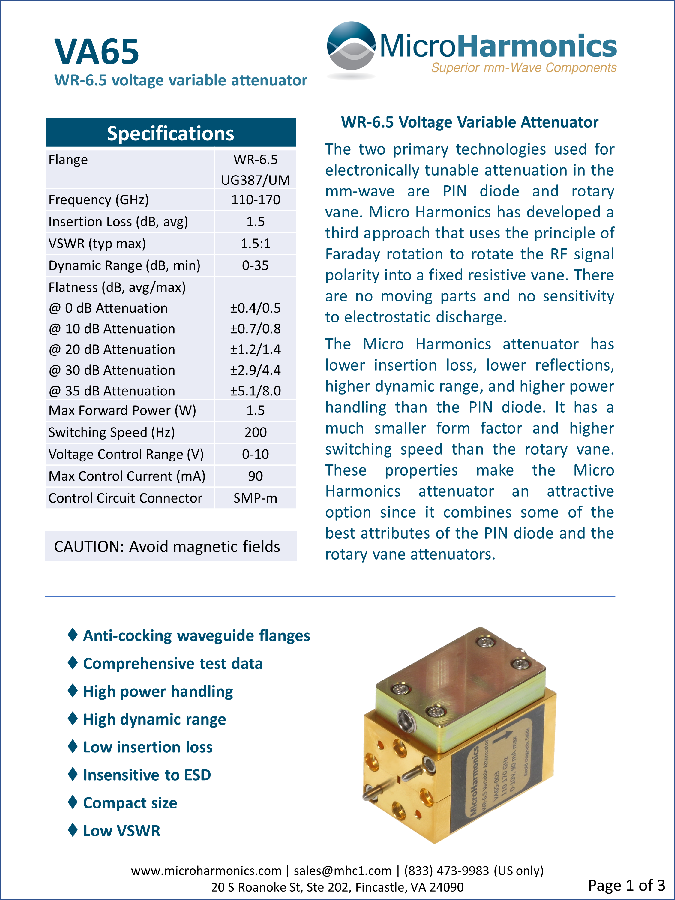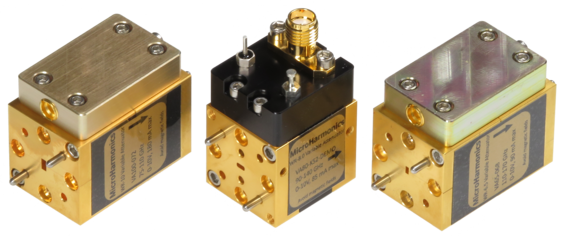
Refer to the table and spec sheets below for more information on the performance of the variable attenuators. Check out our blog post to see a comparison between our Faraday rotation variable attenuator approach and the other approaches available.
Voltage Variable Attenuators
| Model | Flange (EIA) | Band (GHz) | Dynamic Range (dB, Min) | Insertion Loss (dB, Avg) | Max Power (W) |
|---|---|---|---|---|---|
| VA148 (TBD*) | WR-15 | 50 – 75 | |||
| VA122 (TBD*) | WR-12 | 60 – 90 | |||
| VA100 | Spec Sheet | WR-10 | 75 – 110 | 0 – 35 | 1.2 | 2.3 |
| VA080 | Spec Sheet | WR-8 | 90 – 140 | 0 – 30 | 0.8 | 2.4 |
| VA065 | Spec Sheet | WR-6.5 | 110 – 170 | 0 – 35 | 1.5 | 1.5 |
| VA051 (TBD*) | WR-5.1 | 140 – 220 | |||
| VA043 (TBD*) | WR-4.3 | 170 – 260 | |||
| VA034 (TBD*) | WR-3.4 | 220 – 325 |
*A full line of voltage variable attenuators will be developed in accordance with market needs. If you have a need for a full band voltage variable attenuator in any of the undeveloped bands, please let us know at sales@mhc1.com or click here!
Voltage variable attenuators (VA) find wide application in many microwave and millimeter-wave systems. At frequencies above 50 GHz, most voltage variable attenuators are either based on pin diodes or resistive vanes with motor driven mechanical actuators. PIN diode attenuators are available up to the WR-6.5 band (110-170 GHz). However, the dynamic range of the WR-6.5 PIN attenuators is only 20 dB, the return loss is near 6 dB, and the power handling is only 6 mW. Transistor chip attenuators are available with good performance to 100 GHz, but the maximum power rating is only 30 mW. The chip must be mounted to a circuit and integrated into the waveguide.
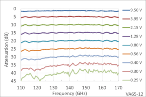
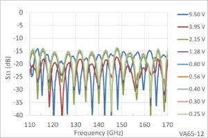
The measured port reflections are shown in the graph below. The VSWR is less than 1.5:1 at the highest attenuation levels.
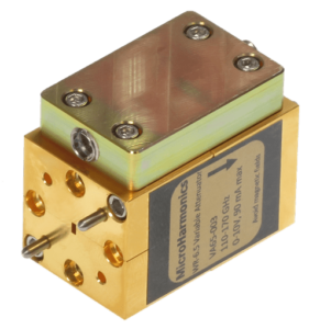 |
| WR-6.5 Attenuator |
The photograph to the left shows our WR-6.5 millimeter wave attenuator. The millimeter wave attenuator is compact with the main body measuring only 0.75 x 0.75 x 1.2 inch (19 x 19 x 30 mm). The small size makes the millimeter wave attenuators very easy to fit into millimeter-wave systems. A DC control voltage is applied through an SMP connector. The switching speed is estimated to be a few kilohertz due to the relatively large inductance of the magnetic coil.
Micro Harmonics designs and manufactures all products in the United States. In addition to millimeter wave attenuators, we make millimeter wave isolators and millimeter wave circulators as well. We do reliability testing (Belcore) and cryogenic cycling tests. Nylon thread lockers are used to ensure that our components stay assembled in the field. Every component is thoroughly RF tested, and the data is shared with the customer. Our components are fully warranted.
When you purchase a Micro Harmonics component, rest assured that you are receiving the highest quality and best performance available on the global commercial market. If you have any questions, don’t hesitate to contact us.

