Background & Design
Commercial Faraday rotation isolators have been around since the 1960’s. Traditional builds have good isolation throughout the microwave and millimeter-wave bands (typically > 20 dB and in many cases > 30 dB across the band). The insertion loss is relatively low in the microwave bands, but steadily increases with frequency. At mm-wave frequencies the insertion loss becomes problematic. For example, in the WR‑10 band (75-110 GHz) the insertion loss can exceed 3 dB, precluding their use in many systems. In the WR-5.1 band (140-220 GHz) the insertion loss can be more than 5 dB. There are very few manufacturers in the bands above 50 GHz. Micro Harmonics is the only manufacturer of isolators in the WR-4.3 (170-260 GHz) and WR-3.4 (220-330 GHz) bands and we are working on designs for the WR-2.8 (260-400 GHz) and WR-2.2 (330-500 GHz) bands. At these high-frequencies the constituent parts are very small and difficult to fabricate and align.
At Micro Harmonics we design isolators that are optimized for low-insertion loss. The typical insertion loss is about 1 dB for our WR-10 isolators and about 2 dB for our WR-3.4 isolators. These numbers are game changers and mm-wave and terahertz system developers are now reconsidering their use. So how do we do it? There are many factors to consider, but here we focus primarily on:
- Minimizing Ferrite Loss
- Minimizing Waveguide Loss
- Precision Fabrication and Alignment
1) Minimizing Ferrite Loss
A good starting point is to consider the equation for EM field rotation in a Faraday rotation isolator.
 |
Where,
- 4πMZ is the axial magnetization
- ϒ is the gyromagnetic ratio
- l is the ferrite length
- c is the speed of light
- ε is the ferrite dielectric constant
This equation shows that the field rotation is directly proportional to the ferrite length and the axial magnetization. Increasing the magnetic bias field increases the rate of rotation until the ferrite becomes saturated (4πMz = 4πMs). Beyond saturation, further increases in the magnetic bias field have no effect.
Minimum insertion loss and maximum isolation occur when the EM field is rotated by 45° as it passes through the ferrite. The traditional method used to tune Faraday rotation isolators is to use ferrites that are substantially longer than the minimum required length and then tune the magnetic bias field to achieve optimal performance. This approach works very well at the lower frequencies. But at the higher mm-wave frequencies ferrites become very lossy. To minimize loss in mm-wave isolators it is essential that the ferrite length be reduced as much as possible. At Micro Harmonics we use a saturating magnetic bias field and the minimum possible ferrite length to achieve 45° rotation.
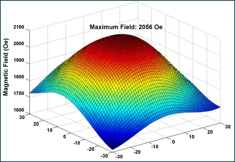
We measure our magnetic bias fields to insure the ferrites are saturated. We use magnetic armatures to achieve a focused, uniform bias field in the ferrite. The graph below shows the measured magnetic bias field near the surface of the ferrite core. The peak measured value of 2000 Oe is substantially more than what is required for saturation. The measurements extend well outside of the area of the ferrite.
2) Minimizing Waveguide Loss


3) Precision Fabrication and Alignment
There are substantial challenges in fabricating and assembling the isolators at the higher bands. The parts become increasingly smaller and some of the materials, in particular the ferrite and alumina cones, are very difficult to machine. There are very few vendors who will even attempt to fabricate these parts and even the most skilled craftsmen can fail in the end. We have expended a significant amount of time and effort developing techniques to fabricate these parts.
Aside from the myriad fabrication complications there are considerable alignment difficulties that must be overcome. Even a small 1° misalignment of the resistive layer in the cones can reduce the isolation by 10 dB. The area near the ferrite core can support more than twenty modes. Small misalignments can cause significant coupling to the higher order modes resulting in unwanted structure in the response, increased insertion loss and port reflections as well as decreased isolation. Misalignments can also change the orientation of the resistive layers in the cones such that a component of the E-field of the forward travelling wave is in the plane of the resistive layer resulting in increased insertion loss.
The assembly process is an art form. No two isolators have identical signatures. At Micro Harmonics we continually strive to improve our assembly techniques and the uniformity of our assemblies. But most importantly, we comprehensively test every isolator on a vector network analyzer to insure it meets our specifications. We supply this measured data to our customers. Many competitors spot check their components on less sophisticated systems which can lead to erroneous test data and missed signatures in the response.
“Typical” Specifications

The definition of “typical” used by our competitors is often unknown and may vary widely. But at Micro Harmonics, we have clearly defined our specifications, which you can read about here. Furthermore, we provide comprehensive test data for every component we sell. The only surefire way to know what you are getting is to test the isolator at many points across the band. It is highly advisable to obtain test data from the manufacturer prior to purchasing an isolator, particularly for isolators operating at millimeter-wave frequencies. A “typical” dataset is no substitute for the data for the specific isolator you are purchasing.
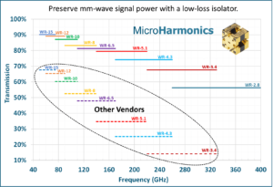
The chart above shows the insertion loss of Micro Harmonics isolators versus the insertion loss of competitor products. At WR-2.8, there is no competitor product.
Summary
Micro Harmonics isolators use modern, innovative designs that yield the industry’s lowest insertion loss. Additionally, we use diamond heatsinks that channel heat from the resistive layers in the cones to the waveguide block. The result is cooler operating temperatures and improved reliability. To our knowledge, no other manufacturer does this. Our low-loss isolators extend all the way to the WR-4.3 (170-260 GHz) and WR-3.4 (220-330 GHz) bands and we are working on designs for the WR-2.8 (260-400 GHz) and WR-2.2 (330-500 GHz) bands. VNA test data at more than 1000 points across the band is included with every isolator that we sell. These components are quickly gaining traction in the US, European, and Asian markets. Our isolators are simply the most advanced ferrite components on the market today. And yet with all these advantages, our components remain competitively priced. Call or email us today to learn more about our products or view the product listing on our website.

